| Installation Special Tool(s) General Equipment Two M10 x 60 mm locating studs Transmission jack Materials Name Specification Grease ESD-M2C220-A Installation All Vehicles | | -
Check the pilot bearing for damage. If damaged, install a new pilot bearing
For additional information, refer to: Pilot Bearing (308-01A Clutch - Vehicles With: MT-75, Removal and Installation).
| | | -
NOTE:Do not apply grease to a newly installed pilot bearing. Apply approximately one gram of grease to the pilot bearing. | | | -
Apply a thin film of grease to the input shaft guide sleeve. | | | -
Shift the transmission into third gear. | | | -
CAUTION:Do not tilt the transmission during installation. This may cause damage to the pilot bearing. | | | -
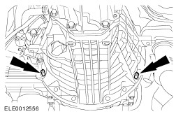
NOTE:Do not fully tighten the transmission retaining bolts at this stage. Install one transmission retaining bolt to the right-hand side and one to the left-hand side. | | | -
Remove the locating studs. | | | -
Install the remaining transmission retaining bolts to the right-hand side. | | | -
Install the remaining transmission retaining bolts to the left-hand side. | | | -
Connect the crankshaft position (CKP) sensor electrical connector and attach the shield. | | | -
Connect the reversing lamp switch and the vehicle speed sensor (VSS) electrical connectors. | | | -
CAUTION:If brake fluid comes into contact with the paintwork, rinse off the affected areas with cold water without delay. Connect the clutch slave cylinder pipe. | | | -
Bleed the clutch system.
For additional information, refer to: Clutch System Bleeding - Vehicles With: 5-Speed Manual Transmission (MT-75) (308-00 Manual Transmission/Transaxle and Clutch - General Information, General Procedures).
| Vehicles with tachograph | | -
Connect the tachograph sensor electrical connector. | All vehicles | | -
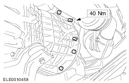
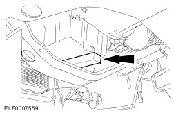
Raise the front axle crossmember and tighten the four retaining bolts (left-hand side shown). | | | -
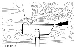
NOTE:When using a two post lift. Remove the wooden block. | | | -
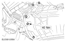
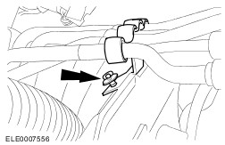
Install the transmission support insulator. - Install all retaining bolts.
- Tighten the front axle to bracket retaining bolts.
- Tighten the bracket to transmission retaining bolts.
| | | -
NOTE:When using a four post lift. | | | -
Install the gearshift cables. | | | -
Install the exhaust muffler. | Vehicles with auxiliary heating | | -
Attach the power steering lines to the front axle crossmember. | All vehicles | | -
WARNING:Install a new steering column flexible coupling nut. Failure to follow this instruction may result in personal injury. NOTE:Make sure the road wheels are in the straight ahead position. Connect the steering column flexible coupling to the steering gear pinion. | | | -
CAUTION:Install new bolts. NOTE:Align the mark on the driveshaft flange with the mark on the transmission output shaft flange. Attach the driveshaft to the transmission output shaft flange. | | | -
CAUTION:Install new bolts. Tighten the driveshaft front center bearing retaining bolts. | | | -
Connect the battery ground cable.
For additional information, refer to: Battery Disconnect and Connect (414-01 Battery, Mounting and Cables, General Procedures).
| | | -
Adjust the gearshft cables.
For additional information, refer to: Gearshift Cables (308-06A Manual Transmission/Transaxle External Controls - Vehicles With: MT-75, Removal and Installation).
| | | -
Check the front toe adjustment, adjust if necessary.
For additional information, refer to: Specifications (204-00 Suspension System - General Information, Specifications).
| |