| Disassembly and Assembly of Subassemblies Special Tool(s) | | Remover, Mainshaft Needle Bearing Sleeve 308 - 191 (16 - 056) | General Equipment Materials Name Specification Manual transmission fluid WSD - M2C200 - C Disassembly | | -
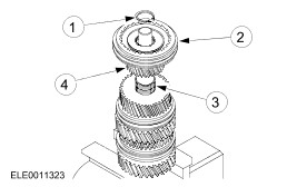
CAUTION:Mark the position of the synchronizer rings in relation to the synchronizer units to aid installation. Remove the input shaft and fourth gear synchronizer ring from the output shaft. - Remove the output shaft locating bearing.
| | | -
Remove the fifth gear wheel and synchronizer ring from the output shaft. - Remove the gear wheel.
- Remove the gear synchronizer ring.
- Remove the needle roller bearing.
| | | -
WARNING:Do not allow the synchronizers to fall apart. Failure to follow these instructions may result in personal injury. CAUTION:Use soft jaws for all operations in a vise. NOTE:Clamp the output shaft in a vise with the output end. Remove the third/fourth gear synchronizer unit together with the third gear wheel. - Remove the circlip.
- Third/fourth gear synchronizer.
- Needle roller bearing.
- Third gear wheel.
| | | -
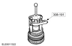
Using the special tool, remove the third gear bearing ring. - Locate the special tool in the recesses off the bearing ring.
| | | -
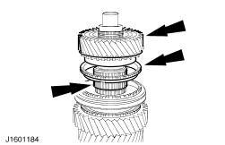
NOTE:Mark the position of the second gear wheel in relation to the synchronizer ring to aid installation. Remove the second gear wheel, the needle roller bearing and synchronizer ring. | | | -
NOTE:Mark the position of the shift ring in relation to the first gear wheel to aid installation.. Components are paired. Remove the first/second gear synchronizer and the first gear wheel. - First/second gear synchronizer.
- First gear wheel.
- Needle roller bearing.
| | | -
NOTE:Mark the position of the shift ring in relation to the reverse gear wheel to aid installation. Components are paired. NOTE:Clamp the output shaft the other way round in the vise. Remove the fifth/reverse gear synchronizer, the reverse gear wheel and needle roller bearing. - Fifth/reverse gear synchronizer.
- Reverse gear wheel.
- Needle roller bearing.
| Assembly | | -
Carefully clean and check all sliding parts and lubricate the synchronizer rings with Manual transmission fluid before assembly. | | | -
Install the needle roller bearing, reverse gear wheel and synchronizer unit. - Install the reverse gear wheel.
- Install the synchronizer.
- Install the snap ring.
| | | -
Install the first/second gear synchronizer unit. - Install the needle roller bearing.
- Install the gear wheel.
- Install the synchronizer unit.
| | | -
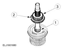
Install the synchronizer ring, needle roller bearing and second gear wheel. - Install the needle roller bearing.
- Install the synchronizer ring.
- Install the gear wheel.
| | | -
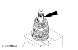
NOTE:Slide the inner bearing ring onto the output shaft as far as the shoulder. NOTE:Install a new inner bearing ring and needle bearing. Using a hot air gun heat the inner bearing ring to approximately 100 ° C and install it. | | | -
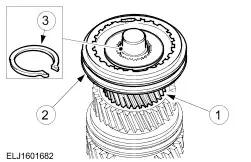
NOTE:Install the synchronizer with the small collar upwards. NOTE:Install the needle roller bearing. Install the third/fourth gear synchronizer. - Install the gear wheel.
- Install the synchronizer.
- Install the circlip.
| | | -
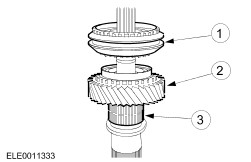
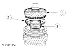
Install the fifth gear wheel. - Install the needle roller bearing.
- Install the synchronizer ring.
- Install the gear wheel.
| | | -
Install the output shaft locating bearing, synchronizer ring and the input shaft. | |