| Diagnosis and Testing Special Tool(s) | | Test and Deployment Lead, Air Bag/Pyrotechnic Safety Belt 418-S055 (40-007) | | | Test and Deployment Lead; Driver and Passenger Air Bag Module 418–525 | | | Test and Deployment Lead, Side Air Bag Module 418–142 | | | Simulator, Driver and Passenger Air Bags 501-073A | | | Simulator, Side Air Bag 501-075 | | | Simulator, Driver Safety Belt Retractor and Pretensioner 418-037 | General Equipment Ford approved diagnostic tool Diagnosing Customer Concerns Without Hard DTCs WARNING:The back up power supply must be depleted, before any work is carried out on the SRS. Wait at least one minute after disconnecting the battery ground cable. Failure to follow this instruction may result in personal injury. NOTE:Following the pinpoint tests when a diagnostic trouble code (DTC) is not present, or the air bag warning lamp is not permanently illuminated, will result in needless replacement of air bag system components and repeat repairs. Speak with the customer to determine if a particular set of conditions must be met in order for a fault to occur. If an illuminated air bag warning lamp is reported by the customer but is not present when the vehicle comes in for repair, pinpoint test diagnostics cannot be used. Diagnosing Customer Concerns with Hard DTCs WARNING:Do not use substitute air bag simulators when working on the SRS. Use only the appropriate tool. Failure to follow this instruction may result in personal injury. Most air bag system diagnostic procedures require the use of system deactivation and system reactivation procedures. These procedures require the air bag module(s) and safety belt buckle pretensioners to be disconnected from the SRS, thereby removing the risk of air bag deployment while diagnostics are carried out. Air bag simulators are required to carry out diagnosis and testing of the air bag system. The simulator contains a resistor, used to simulate an air bag module connection to the system. It is not acceptable to short-circuit the air bag module connections with a 0 ohm jumper wire. If a 0 ohm jumper wire is used to short-circuit the air bag module connections, an illuminated air bag warning lamp will be displayed and a DTC logged by the restraints control module (RCM). Deactivation WARNING:The back up power supply must be depleted, before any work is carried out on the SRS. Wait at least one minute after disconnecting the battery ground cable. Failure to follow this instruction may result in personal injury. - Disconnect the battery ground cable.
REFER to: Battery Disconnect and Connect (414-01 Battery, Mounting and Cables, General Procedures).
- Wait 1 minute for the backup power supply in the RCM to deplete its stored energy.
WARNING:Place the air bag module on a ground wired bench, with the trim cover facing up to avoid accidental deployment. Failure to follow this instruction may result in personal injury. - Remove the driver air bag module from the vehicle.
REFER to: Driver Air Bag Module (501-20B Supplemental Restraint System, Removal and Installation).
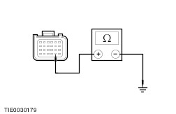
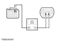
- Connect the air bag simulator to the sub-harness in place of the driver air bag module at the top of the steering column.
- Disconnect the passenger air bag module electrical connector.
REFER to: Passenger Air Bag Module (501-20B Supplemental Restraint System, Removal and Installation).
- Connect the air bag simulator to the wiring harness in place of the passenger air bag module.
- Disconnect the driver side air bag module electrical connector.
- Connect the side air bag module simulator to the driver side air bag module electrical connector in place of the side air bag module.
- Detach the B-pillar trim panel to gain access to the driver safety belt retractor pretensioner electrical connector.
REFER to: B-Pillar Trim Panel (501-05 Interior Trim and Ornamentation, Removal and Installation).
- Disconnect the driver safety belt retractor pretensioner electrical connector.
- Connect the driver safety belt retractor pretensioner simulator to the wiring harness in place of the driver safety belt retractor pretensioner.
- Disconnect the passenger side air bag module electrical connector.
- Connect the side air bag module simulator to the passenger side air bag module electrical connector in place of the side air bag module.
- Detach the B-pillar trim panel to gain access to the passenger safety belt retractor pretensioner electrical connector.
REFER to: B-Pillar Trim Panel (501-05 Interior Trim and Ornamentation, Removal and Installation).
- Disconnect the passenger safety belt retractor pretensioner electrical connector.
- Connect the passenger safety belt retractor pretensioner simulator to the wiring harness in place of the passenger safety belt retractor and pretensioner.
- Connect the battery ground cable.
REFER to: Battery Disconnect and Connect (414-01 Battery, Mounting and Cables, General Procedures).
Reactivation WARNING:The air bag simulators must be removed and the air bag modules reconnected when reactivated to avoid non-deployment in a collision. Failure to follow this instruction may result in personal injury. - Disconnect the battery ground cable.
REFER to: Battery Disconnect and Connect (414-01 Battery, Mounting and Cables, General Procedures).
- Wait 1 minute for the backup power supply in the RCM to deplete its stored energy.
- Remove the driver air bag simulator from the driver air bag module wiring harness at the top of the steering column.
- Connect and install the driver air bag module.
REFER to: Driver Air Bag Module (501-20B Supplemental Restraint System, Removal and Installation).
- Remove the passenger air bag simulator from the passenger air bag module harness.
- Connect and install the passenger air bag module.
REFER to: Passenger Air Bag Module (501-20B Supplemental Restraint System, Removal and Installation).
- Remove the driver side air bag module simulator from the driver side air bag module electrical connector.
- Connect the driver side air bag module electrical connector.
- Remove the driver safety belt retractor pretensioner simulator from the driver safety belt retractor pretensioner wiring harness.
- Connect the driver safety belt retractor pretensioner electrical connector.
- Attach the B-pillar trim panel.
REFER to: B-Pillar Trim Panel (501-05 Interior Trim and Ornamentation, Removal and Installation).
- Remove the passenger side air bag module simulator from the passenger side air bag module electrical connector.
- Connect the passenger side air bag module electrical connector.
- Remove the passenger safety belt retractor pretensioner simulator from the passenger safety belt retractor pretensioner wiring harness.
- Connect the passenger safety belt retractor pretensioner electrical connector.
- Attach the B-pillar trim panel.
REFER to: B-Pillar Trim Panel (501-05 Interior Trim and Ornamentation, Removal and Installation).
- Connect the battery ground cable.
REFER to: Battery Disconnect and Connect (414-01 Battery, Mounting and Cables, General Procedures).
Glossary Air Bag Simulator Air bag simulators are used to simulate air bag module connections to the system. Deactivate the System Deactivate the system means to carry out the deactivation procedure. REFER to Deactivation in this procedure. Prove Out the System The air bag warning indicator will illuminate for 3 seconds. Reactivate the System Reactivate the system means to carry out the reactivation procedure. REFER to Reactivation in this procedure. Principles of Operation SRS (SRS) Operation The vehicle is equipped with DC fired single point sensing system. Vehicles equipped with side air bags are equipped with side impact sensors. In the event of a severe frontal or 3-quarter frontal impact, in excess of a predetermined limit, the driver and passenger (if equipped) front air bag(s) will deploy. In the event of a severe full side impact, in excess of a predetermined limit, either the driver or passenger side air bags (if equipped) will deploy. Air bag deployment will only occur, in the event of a severe collision when the ignition key is in the RUN position. RCM The RCM retains full control of the whole system. Providing continual system checks and full diagnostic capabilities, the non-volatile memory stores the fault codes, which are down loaded through the diagnostic link connector to the Ford approved diagnostic tool. A visual warning indicator which is housed within the instrument cluster, is illuminated when the ignition is switched ON for 3 seconds then goes out. If a fault occurs the warning indicator remains illuminated after a further 5 seconds. The RCM provides an auxiliary power supply, sufficient to deploy the air bag(s) for a minimum of 150mS, in the event of a failure in the vehicle power supply during or after an accident. The auxiliary power supply is discharged by the RCM within 60 seconds of the battery ground cable being disconnected. Thus making sure the SRS remains operational. The RCM contains an electronic acceleration sensor to evaluate and process impact data from the frontal direction and a micromachine sensor that acts as the safing sensor for frontal impacts. Provided both the safing sensor and the electronic acceleration sensor detect an impact in excess of a predetermined limit the RCM initiates the circuit to deploy the frontal air bags. Side Impact Sensors The side impact sensors contain an acceleration sensor, filter, amplifier and an application specific integrated circuit for signal transmitting. The side impact sensor processes the impact data against stored data. In the event of a side impact, in excess of a predetermined limit, the side impact sensor will send a signal to the RCM. The sensor opposite the impact side acts as the safing sensor for lateral impacts. If the electronic acceleration sensor also detects a side impact, in excess of a predetermined limit, a signal is then sent from the RCM to deploy the side air bags (if equipped). Air Bag Warning Indicator The air bag warning indicator is incorporated into the instrument cluster, together with the automatic detach detect (ADD) circuit, the air bag warning indicator comes on for 3 seconds at key ON. If the system self tests OK the air bag warning indicator extinguishes, if a fault is detected the air bag warning indicator will illuminate continually from key ON or not illuminate at all, depending on the nature of the fault. The RCM retaining bolts are part of the ground circuit. The ADD circuit is designed to illuminate the air bag warning indicator continuously, if the RCM circuit is broken, either by: - Loss of the RCM power supply.
- Loss of the RCM ground circuit.
- Disconnection of the RCM electrical connector.
Diagnostic evaluation of the SRS can be made through the data link connector (DLC) and Ford approved diagnostic tool to establish the nature of the concern. Inspection and Verification - Verify the customer concern.
- Visually inspect for obvious signs of mechanical or electrical damage.
Visual Inspection Chart | Electrical | - Fuse(s)
- Electrical connector(s)
- Circuit(s)
- Air bag module(s)
| - If an obvious cause for an observed or reported concern is found, correct the cause (if possible) before proceeding to the next step.
- If the cause is not visually evident, connect the Ford approved diagnostic tool to the DLC and select the vehicle to be tested from the THE FORD APPROVED DIAGNOSTIC TOOL menu.
- Retrieve the DTCs and refer to the Symptom Chart.
Symptom Chart Symptom Chart NOTE:It is only allowed to repair circuits between connectors. If damage has occurred within a connector a connector replacement kit, if available, must be installed. If a connector replacement kit is not available a new wiring harness must be installed. Connectors must not be disassembled. | Symptom | Possible Sources | Action | | No communication with the module | * DLC. * RCM. * Circuit(s). | * | | DTC B1231: Longitudinal acceleration threshold exceeded | * Crash data memory full. | NOTE:The crash data memory can be cleared a maximum of five times. * Clear down the crash data memory using the Ford approved diagnostic tool. REPEAT the self-test, CLEAR the DTCs. | | DTC B1317: Battery voltage high | * Charging system. | * CHECK the charging system.
REFER to: Charging System (414-00 Charging System - General Information, Diagnosis and Testing).
REPEAT the self-test, CLEAR the DTCs. | | DTC B1318: Battery voltage low | * Battery. * Charging system. * Circuit(s). | * | | DTC B1342: RCM is defective | * RCM. | * INSTALL a new RCM.
REFER to: Restraints Control Module (RCM) (501-20B Supplemental Restraint System, Removal and Installation).
REPEAT the self-test, CLEAR the DTCs. | | DTC B1868: Air bag warning indicator open circuit or short to ground | * Instrument cluster. | * CHECK the instrument cluster.
REFER to: Instrument Cluster (413-01 Instrument Cluster, Diagnosis and Testing).
| | DTC B1877: Driver side safety belt pretensioner open circuit | * Driver side safety belt pretensioner. * Circuit(s). | * | | DTC B1878: Passenger side safety belt pretensioner open circuit | * Passenger side safety belt pretensioner. * Circuit(s). | * | | DTC B1879: Driver side safety belt pretensioner short to ground | * Driver side safety belt pretensioner. * Circuit(s). | * | | DTC B1881: Passenger side safety belt pretensioner open circuit | * Passenger side safety belt pretensioner. * Circuit(s). | * | | DTC B1882: Passenger side safety belt pretensioner short to battery | * Passenger side safety belt pretensioner. * Circuit(s). | * | | DTC B1883: Passenger side safety belt pretensioner short to ground | * Passenger side safety belt pretensioner. * Circuit(s). | * | | DTC B1885: Driver side safety belt pretensioner low resistance | * Driver side safety belt pretensioner. * Circuit(s). | * | | DTC B1886: Passenger side safety belt pretensioner low resistance | * Passenger side safety belt pretensioner. * Circuit(s). | * | | DTC B1916: Driver air bag short to battery | * Driver air bag module. * Clockspring. * Circuit(s). | * | | DTC B1925: Passenger air bag short to battery | * Circuit(s). | * | | DTC B1932: Driver air bag open circuit or high resistance | * Driver air bag module. * Clockspring. * Circuit(s). | * | | DTC B1933: Passenger air bag open circuit or high resistance | * Passenger air bag module. * Circuit(s). | * | | DTC B1934: Driver air bag circuit low resistance | * Driver air bag module. * Clockspring. * Circuit(s). | * | | DTC B1935: Passenger air bag circuit low resistance | * Passenger air bag module. * Circuit(s). | * | | DTC B1936: Driver air bag circuit short to ground | * Driver air bag module. * Clockspring. * Circuit(s). | * | | DTC B1938: Passenger air bag circuit short to ground | * Passenger air bag module. * Circuit(s). | * | | DTC B1992: Driver side air bag circuit short to battery | * Circuit(s). | * | | DTC B1993: Driver side air bag circuit short to ground | * Driver side air bag module. * Circuit(s). | * | | DTC B1994: Driver side air bag circuit open circuit | * Driver side air bag module. * Circuit(s). | * | | DTC B1995: Driver side air bag circuit low resistance on squib | * Driver side air bag module. * Circuit(s). | * | | DTC B1996: Passenger side air bag circuit short to battery | * Passenger side air bag module. * Circuit(s). | * | | DTC B1997: Passenger side air bag circuit short to ground | * Passenger side air bag module. * Circuit(s). | * | | DTC B1998: Passenger side air bag circuit open circuit | * Passenger side air bag module. * Circuit(s). | * | | DTC B1999: Passenger side air bag circuit low resistance on squib | * Passenger side air bag module. * Circuit(s). | * | | DTC B2444: Driver side impact sensor internal fault | * Driver side impact sensor. | * INSTALL a new driver side impact sensor.
REFER to: Side Impact Sensor (501-20B Supplemental Restraint System, Removal and Installation).
REPEAT the self-test, CLEAR the DTCs. | | DTC B2445: Passenger side impact sensor internal fault | * Passenger side impact sensor. | * INSTALL a new passenger side impact sensor.
REFER to: Side Impact Sensor (501-20B Supplemental Restraint System, Removal and Installation).
REPEAT the self-test, CLEAR the DTCs. | | DTC B2477: RCM configuration failure | * RCM. | * CONFIGURE the RCM. REFER to the Ford approved diagnostic tool. REPEAT the self-test, CLEAR the DTCs. | | DTC B2792: Cross link between firing circuits | * Circuit(s). | * | | DTC P1796: CAN controller circuit (BUS off) | * Circuit(s). | * | | DTC U0155: Lost communication with instrument cluster control module | * Instrument cluster. | * CHECK the instrument cluster.
REFER to: Instrument Cluster (413-01 Instrument Cluster, Diagnosis and Testing).
REPEAT the self-test, CLEAR the DTCs. | | * Circuit(s). | * CHECK the CAN bus.
REFER to: Communications Network (418-00 Module Communications Network, Diagnosis and Testing).
REPEAT the self-test, CLEAR the DTCs. | | DTC U2017: Driver side impact sensor communications fault | * Driver side impact sensor. | * CHECK the driver side impact sensor calibration. REFER to the Ford approved diagnostic tool. REPEAT the self-test, CLEAR the DTCs. | | * Circuit(s). | * GO to Pinpoint Test AC. REPEAT the self-test, CLEAR the DTCs. | | DTC U2018: Passenger side impact sensor communications fault | * Passenger side impact sensor. | * CHECK the passenger side impact sensor calibration. REFER to the Ford approved diagnostic tool. REPEAT the self-test, CLEAR the DTCs. | | * Circuit(s). | * GO to Pinpoint Test AD. REPEAT the self-test, CLEAR the DTCs. | | RCM disconnected or inoperative | * RCM * Circuit(s). | * | Pinpoint Tests | PINPOINT TEST A : NO COMMUNICATION WITH THE MODULE | NOTE:Use a digital multimeter for all electrical measurements. | | TEST CONDITIONS | DETAILS/RESULTS/ACTIONS | | A1: CHECK THAT THE FORD APPROVED DIAGNOSTIC TOOL IS COMMUNICATING THROUGH THE DLC | | | 1 Select an alternative system to check the DLC. | | | Is the Ford approved diagnostic tool able to communicate with the selected system? Yes No CHECK the DLC. For additional information, refer to the Wiring Diagrams. REPEAT the self-test, CLEAR the DTCs. | | A2: CHECK THE AIR BAG WARNING INDICATOR | | | 1 Ignition switch in position II. | | | 2 The air bag warning indicator should illuminate when the ignition is in the ON position for three seconds and then go out. If a fault is present, the air bag warning light will then will illuminate continually. | | | Is the warning indicator operating? Yes No CHECK the instrument cluster.
REFER to: Instrument Cluster (413-01 Instrument Cluster, Diagnosis and Testing).
| | A3: CHECK THE DLC CIRCUIT | WARNING:Wait at least one minute after disconnecting the battery ground cable before disconnecting any SRS electrical connector. Failure to follow this instruction may result in personal injury. | | | 1 Ignition switch in position 0. | | | 2 Deactivate the SRS. | | | 3 Disconnect RCM CR114A. | | | 4 Measure the resistance between the DLC CDB04 pin 7, circuit VDB10A (GY) and the RCM CR114A pin 17, circuit VDB10D (GY), harness side. | | | Is the resistance less than 5 ohms? Yes INSTALL a new RCM.
REFER to: Restraints Control Module (RCM) (501-20B Supplemental Restraint System, Removal and Installation).
REPEAT the self-test, CLEAR the DTCs. REACTIVATE the system. No REPAIR circuit VDB10A (GY) or circuit VDB10D (GY). REPEAT the self-test, CLEAR the DTCs. REACTIVATE the system. | | PINPOINT TEST B : DTC B1318: BATTERY VOLTAGE LOW | NOTE:Use a digital multimeter for all electrical measurements. | | TEST CONDITIONS | DETAILS/RESULTS/ACTIONS | | B1: CHECK THE BATTERY VOLTAGE | | | 1 Ignition switch in position II. | | | 2 Check the battery voltage with the ignition in the ON position. | | | Is the battery voltage greater than 9 volts? Yes No CHECK the battery and charging system. REFER to: Battery (414-01 Battery, Mounting and Cables, Diagnosis and Testing), Charging System (414-00 Charging System - General Information, Diagnosis and Testing). REPEAT the self-test, CLEAR the DTCs. REACTIVATE the system. | | B2: CHECK THE RCM SUPPLY CIRCUIT | WARNING:Wait at least one minute after disconnecting the battery ground cable before disconnecting any SRS electrical connector. Failure to follow this instruction may result in personal injury. | | | 1 Ignition switch in position 0. | | | 2 Deactivate the SRS. | | | 3 Disconnect RCM CR114A. | | | 4 Ignition switch in position II. | | | 5 Measure the voltage between the: Chassis Cab - RCM CR114A pin 1, circuit SBP68A (RD/GN), harness side and ground.
Van, Bus, Kombi - RCM CR114A pin 1, circuit SBP68A (GN/RD), harness side and ground.
| | | Is the voltage between 9 and 16 volts? Yes No REPAIR circuit SBP68A (RD/GN) or circuit SBP68A (GN/RD). REPEAT the self-test, CLEAR the DTCs. REACTIVATE the system. | | B3: CHECK THE RCM GROUND CIRCUIT | | | 1 Ignition switch in position 0. | | | 2 Measure the resistance between the RCM CR114A pin 20, circuit GD112A (BK/GN), harness side and ground. | | | Is the resistance less than 5 ohms? Yes INSTALL a new RCM.
REFER to: Restraints Control Module (RCM) (501-20B Supplemental Restraint System, Removal and Installation).
REPEAT the self-test, CLEAR the DTCs. REACTIVATE the system. No REPAIR circuit GD112A (BK/GN). REPEAT the self-test, CLEAR the DTCs. REACTIVATE the system. | | PINPOINT TEST C : DTC B1877: SIDE SAFETY BELT PRETENSIONER OPEN CIRCUIT | WARNING:Wait at least one minute after disconnecting the battery ground cable before disconnecting any SRS electrical connector. Failure to follow this instruction may result in personal injury. | NOTE:Use a digital multimeter for all electrical measurements. | | TEST CONDITIONS | DETAILS/RESULTS/ACTIONS | | C1: CHECK THE DRIVER SIDE SAFETY BELT PRETENSIONER CIRCUIT | | | 1 Deactivate the SRS. | | | 2 Ignition switch in position II. | | | 3 Carry out the self-test with the simulators installed. | | | Does the system prove out correctly? Yes No | | C2: PROVE OUT THE DRIVER SIDE SAFETY BELT PRETENSIONER CIRCUIT | | | 1 Ignition switch in position 0. | | | 2 Disconnect Driver Side Safety Belt Retractor Pretensioner Simulator. | | | 3 Connect Driver Side Safety Belt Retractor Pretensioner Electrical Connector CR120. | | | 4 Ignition switch in position II. | | | 5 Carry out the self-test. | | | Does the system prove out correctly? Yes REPEAT the self-test, CLEAR the DTCs. REACTIVATE the system. No INSTALL a new driver side safety belt retractor and pretensioner.
REFER to: Safety Belt Retractor and Pretensioner (501-20A Safety Belt System, Removal and Installation).
REPEAT the self-test, CLEAR the DTCs. REACTIVATE the system. | | C3: CHECK THE DRIVER SIDE SAFETY BELT PRETENSIONER FOR OPEN CIRCUIT OR HIGH RESISTANCE | | | 1 Ignition switch in position 0. | | | 2 Disconnect RCM CR114B. | | | 3 Disconnect Driver Side Safety Belt Pretensioner Simulator. | | | 4 Measure the resistance between the: Chassis Cab - RCM CR114B pin 4, circuit RR201B (BU/OG), harness side and the driver side safety belt retractor pretensioner electrical connector CR120 pin 1, circuit RR201E (BU/OG), harness side.
- RCM CR114B pin 5, circuit RR120B (GN/RD), harness side and the driver side safety belt retractor pretensioner electrical connector CR120 pin 2, circuit RR120E (GN/RD), harness side.
Van, Bus Kombi - RCM CR114B pin 4, circuit RR201B (BU/OG), harness side and the driver side safety belt retractor pretensioner electrical connector CR120 pin 1, circuit RR201D (BU/OG), harness side.
- RCM CR114B pin 5, circuit RR120B (BN/GN), harness side and the driver side safety belt retractor pretensioner electrical connector CR120 pin 2, circuit RR120D (BN/GN), harness side.
| | | Are the resistances less than 5 ohms? Yes REPEAT the self-test, CLEAR the DTCs. REACTIVATE the system. No REPAIR circuit RR120B (GN/RD), or circuit RR120B (BN/GN), or circuit RR120D (BN/GN), or circuit RR120E (GN/RD), or circuit RR201B (BU/OG), or circuit RR201E (BU/OG). REPEAT the self-test, CLEAR the DTCs. REACTIVATE the system. | | PINPOINT TEST D : DTC B1878: DRIVER SIDE SAFETY BELT PRETENSIONER SHORT TO BATTERY | WARNING:Wait at least one minute after disconnecting the battery ground cable before disconnecting any SRS electrical connector. Failure to follow this instruction may result in personal injury. | NOTE:Use a digital multimeter for all electrical measurements. | | TEST CONDITIONS | DETAILS/RESULTS/ACTIONS | | D1: CHECK THE DRIVER SIDE SAFETY BELT PRETENSIONER CIRCUIT | | | 1 Deactivate the SRS. | | | 2 Ignition switch in position II. | | | 3 Carry out the self-test with the simulators installed. | | | Does the system prove out correctly? Yes No | | D2: PROVE OUT THE DRIVER SIDE SAFETY BELT PRETENSIONER CIRCUIT | | | 1 Ignition switch in position 0. | | | 2 Disconnect Driver Side Safety Belt Retractor Pretensioner Simulator. | | | 3 Connect Driver Side Safety Belt Retractor Pretensioner CR120. | | | 4 Ignition switch in position II. | | | 5 Carry out the self-test. | | | Does the system prove out correctly? Yes REPEAT the self-test, CLEAR the DTCs. REACTIVATE the system. No INSTALL a new driver safety belt retractor and pretensioner.
REFER to: Safety Belt Retractor and Pretensioner (501-20A Safety Belt System, Removal and Installation).
REPEAT the self-test, CLEAR the DTCs. REACTIVATE the system. | | D3: CHECK THE DRIVER SIDE SAFETY BELT PRETENSIONER FOR A SHORT TO BATTERY | | | 1 Ignition switch in position 0. | | | 2 Disconnect RCM CR114B. | | | 3 Disconnect Driver Safety Belt Pretensioner Simulator. | | | 4 Ignition switch in position II. | | | 5 Measure the voltage between the: Chassis Cab - RCM CR114B pin 4, circuit CR201B (BU/OG), harness side and ground.
- RCM CR114B pin 5, circuit RR120B (GN/RD), harness side and ground.
Van, Bus, Kombi - RCM CR114B pin 4, circuit CR201B (BU/OG), harness side and ground.
- RCM CR114B pin 5, circuit RR120B (BN/GN), harness side and ground.
| | | Is any voltage present? Yes REPAIR circuit RR120B (GN/RD), or circuit RR120B (BN/GN), or circuit CR201B (BU/OG). REPEAT the self-test, CLEAR the DTCs. REACTIVATE the system. No REPEAT the self-test, CLEAR the DTCs. REACTIVATE the system. | | PINPOINT TEST E : DTC B1879: DRIVER SIDE SAFETY BELT PRETENSIONER SHORT TO GROUND | WARNING:Wait at least one minute after disconnecting the battery ground cable before disconnecting any SRS electrical connector. Failure to follow this instruction may result in personal injury. | NOTE:Use a digital multimeter for all electrical measurements. | | TEST CONDITIONS | DETAILS/RESULTS/ACTIONS | | E1: CHECK THE DRIVER SIDE SAFETY BELT PRETENSIONER CIRCUIT | | | 1 Deactivate the SRS. | | | 2 Ignition switch in position II. | | | 3 Carry out the self-test with the simulators installed. | | | Does the system prove out correctly? Yes No | | E2: PROVE OUT THE DRIVER SIDE SAFETY BELT PRETENSIONER CIRCUIT | | | 1 Ignition switch in position 0. | | | 2 Disconnect Driver Side Safety Belt Retractor Pretensioner Simulator. | | | 3 Connect Driver Side Safety Belt Retractor Pretensioner CR120. | | | 4 Ignition switch in position II. | | | 5 Carry out the self-test. | | | Does the system prove out correctly? Yes REPEAT the self-test, CLEAR the DTCs. No INSTALL a new driver safety belt retractor and pretensioner.
REFER to: Safety Belt Retractor and Pretensioner (501-20A Safety Belt System, Removal and Installation).
REPEAT the self-test, CLEAR the DTCs. REACTIVATE the system. | | E3: CHECK THE DRIVER SIDE SAFETY BELT PRETENSIONER FOR A SHORT TO GROUND | | | 1 Ignition switch in position 0. | | | 2 Disconnect RCM CR114A. | | | 3 Disconnect RCM CR114B. | | | 4 Disconnect Driver Side Safety Belt Retractor Pretensioner Simulator. | | | 5 Measure the resistance between the: Chassis Cab - RCM CR114B pin 4, circuit CR201B (BU/OG), harness side and ground.
- RCM CR114B pin 5, circuit RR120B (GN/RD), harness side and ground.
- RCM CR114A pin 20, circuit GD112A (BK/GN), harness side and the RCM CR114B pin 4, circuit CR201B (BU/OG) harness side.
- RCM CR114A pin 20, circuit GD112A (BK/GN), harness side and the RCM CR114B pin 5, circuit RR120B (GN/RD), harness side.
Van, Bus, Kombi - RCM CR114B pin 4, circuit CR201B (BU/OG), harness side and ground.
- RCM CR114B pin 5, circuit RR120B (BN/GN), harness side and ground.
- RCM CR114A pin 20, circuit GD112A (BK/GN), harness side and the RCM CR114B pin 4, circuit CR201B (BU/OG) harness side.
- RCM CR114A pin 20, circuit GD112A (BK/GN), harness side and the RCM CR114B pin 5, circuit RR120B (BN/GN), harness side.
| | | Are the resistances greater than 10,000 ohms? Yes REPEAT the self-test, CLEAR the DTCs. REACTIVATE the system. No REPAIR circuit RR120B (GN/RD), or circuit RR120B (BN/GN), or circuit GD112A (BK/GN), or circuit CR201B (BU/OG). REPEAT the self-test, CLEAR the DTCs. REACTIVATE the system. | | PINPOINT TEST F : DTC B1881: PASSENGER SIDE SAFETY BELT PRETENSIONER OPEN CIRCUIT | WARNING:Wait at least one minute after disconnecting the battery ground cable before disconnecting any SRS electrical connector. Failure to follow this instruction may result in personal injury. | NOTE:Use a digital multimeter for all electrical measurements. | | TEST CONDITIONS | DETAILS/RESULTS/ACTIONS | | F1: CHECK THE PASSENGER SIDE SAFETY BELT PRETENSIONER CIRCUIT | | | 1 Deactivate the SRS. | | | 2 Ignition switch in position II. | | | 3 Carry out the self-test with the simulators installed. | | | Does the system prove out correctly? Yes No | | F2: PROVE OUT THE PASSENGER SIDE SAFETY BELT PRETENSIONER CIRCUIT | | | 1 Ignition switch in position 0. | | | 2 Disconnect Passenger Side Safety Belt Retractor Pretensioner Simulator. | | | 3 Connect Passenger Side Safety Belt Retractor Pretensioner CR122. | | | 4 Ignition switch in position II. | | | 5 Carry out the self-test. | | | Does the system prove out correctly? Yes REPEAT the self-test, CLEAR the DTCs. REACTIVATE the system. No INSTALL a new passenger safety belt retractor and pretensioner.
REFER to: Safety Belt Retractor and Pretensioner (501-20A Safety Belt System, Removal and Installation).
REPEAT the self-test, CLEAR the DTCs. REACTIVATE the system. | | F3: CHECK THE PASSENGER SIDE SAFETY BELT PRETENSIONER FOR OPEN CIRCUIT OR HIGH RESISTANCE | | | 1 Ignition switch in position 0. | | | 2 Disconnect RCM CR114B. | | | 3 Disconnect Passenger Side Safety Belt Retractor Pretensioner Simulator. | | | 4 Measure the resistance between the: Chassis Cab - RCM CR114B pin 6, circuit RR122B (BU/RD), harness side and the passenger side safety belt retractor pretensioner CR122 pin 2, circuit RR122E (BU/RD), harness side.
- RCM CR114B pin 12, circuit CR203B (GY/VT), harness side and the passenger side safety belt retractor pretensioner CR122 pin 1, circuit CR203E (GY/VT), harness side.
Van, Bus, Kombi - RCM CR114B pin 6, circuit RR122A (BN), harness side and the passenger side safety belt retractor pretensioner CR122 pin 2, circuit RR122D (BN), harness side.
- RCM CR114B pin 12, circuit CR203A (GY/VT), harness side and the passenger side safety belt retractor pretensioner CR122 pin 1, circuit CR203D (GY/VT), harness side.
| | | Are the resistances less than 5 ohms? Yes REPEAT the self-test, CLEAR the DTCs. REACTIVATE the system. No REPAIR circuit RR122A (BN), or circuit RR122B (BU/RD), or circuit RR122E (BU/RD), or circuit CR203B (GY/VT), or circuit CR203E (GY/VT). REPEAT the self-test, CLEAR the DTCs. REACTIVATE the system. | | PINPOINT TEST G : DTC B1882: PASSENGER SIDE SAFETY BELT PRETENSIONER SHORT TO BATTERY | WARNING:Wait at least one minute after disconnecting the battery ground cable before disconnecting any SRS electrical connector. Failure to follow this instruction may result in personal injury. | NOTE:Use a digital multimeter for all electrical measurements. | | TEST CONDITIONS | DETAILS/RESULTS/ACTIONS | | G1: CHECK THE PASSENGER SIDE SAFETY BELT PRETENSIONER CIRCUIT | | | 1 Deactivate the SRS. | | | 2 Ignition switch in position II. | | | 3 Carry out the self-test with the simulators installed. | | | Does the system prove out correctly? Yes No | | G2: PROVE OUT THE PASSENGER SIDE SAFETY BELT PRETENSIONER CIRCUIT | | | 1 Ignition switch in position 0. | | | 2 Disconnect Passenger Side Safety Belt Retractor Pretensioner Simulator. | | | 3 Connect Passenger Side Safety Belt Retractor Pretensioner CR122. | | | 4 Ignition switch in position II. | | | 5 Carry out the self-test. | | | Does the system prove out correctly? Yes REPEAT the self-test, CLEAR the DTCs. REACTIVATE the system. No INSTALL a new RCM.
REFER to: Restraints Control Module (RCM) (501-20B Supplemental Restraint System, Removal and Installation).
REPEAT the self-test, CLEAR the DTCs. REACTIVATE the system. | | G3: CHECK THE PASSENGER SIDE SAFETY BELT PRETENSIONER FOR A SHORT TO BATTERY | | | 1 Ignition switch in position 0. | | | 2 Disconnect RCM CR114B. | | | 3 Disconnect Passenger Side Safety Belt Retractor Pretensioner Simulator. | | | 4 Ignition switch in position II. | | | 5 Measure the voltage between the: Chassis Cab - RCM CR114B pin 6, circuit RR122B (BU/RD), harness side and ground.
- RCM CR114B pin 12, circuit CR203B (GY/VT), harness side and ground.
Van, Bus, Kombi - RCM CR114B pin 6, circuit RR122A (BN), harness side and ground.
- RCM CR114B pin 12, circuit CR203A (GY/VT), harness side and ground.
| | | Is any voltage present? Yes REPAIR circuit RR122A (BN), or circuit RR122B (BU/RD), or circuit CR203A (GY/VT), or circuit CR203B (GY/VT). REPEAT the self-test, CLEAR the DTCs. REACTIVATE the system. No REPEAT the self-test, CLEAR the DTCs. REACTIVATE the system. | | PINPOINT TEST H : DTC B1883: PASSENGER SIDE SAFETY BELT PRETENSIONER SHORT TO GROUND | WARNING:Wait at least one minute after disconnecting the battery ground cable before disconnecting any SRS electrical connector. Failure to follow this instruction may result in personal injury. | NOTE:Use a digital multimeter for all electrical measurements. | | TEST CONDITIONS | DETAILS/RESULTS/ACTIONS | | H1: CHECK THE PASSENGER SIDE SAFETY BELT PRETENSIONER CIRCUIT | | | 1 Deactivate the SRS. | | | 2 Ignition switch in position II. | | | 3 Carry out the self-test with the simulators installed. | | | Does the system prove out correctly? Yes No | | H2: PROVE OUT THE PASSENGER SIDE SAFETY BELT PRETENSIONER CIRCUIT | | | 1 Ignition switch in position 0. | | | 2 Disconnect Passenger Side Safety Belt Retractor Pretensioner Simulator. | | | 3 Connect Passenger Side Safety Belt Retractor Pretensioner CR122. | | | 4 Ignition switch in position II. | | | 5 Carry out the self-test. | | | Does the system prove out correctly? Yes REPEAT the self-test, CLEAR the DTCs. REACTIVATE the system. No INSTALL a new passenger side safety belt retractor and pretensioner.
REFER to: Safety Belt Retractor and Pretensioner (501-20A Safety Belt System, Removal and Installation).
REPEAT the self-test, CLEAR the DTCs. REACTIVATE the system. | | H3: CHECK THE PASSENGER SIDE SAFETY BELT PRETENSIONER CIRCUIT FOR A SHORT TO GROUND | | | 1 Ignition switch in position 0. | | | 2 Disconnect RCM CR114B. | | | 3 Disconnect Passenger Side Safety Belt Retractor Pretensioner Simulator. | | | 4 Measure the resistance between the: Chassis Cab - RCM CR114B pin 6, circuit RR122B (BU/RD), harness side and ground.
- RCM CR114B pin 12, CR203B (GY/VT), harness side and ground.
Van, Bus, Kombi - RCM CR114B pin 6, circuit RR122A (BN), harness side and ground.
- RCM CR114B pin 12, circuit CR203A (GY/VT), harness side and ground.
| | | Are the resistances greater than 10,000 ohms? Yes REPEAT the self-test, CLEAR the DTCs. REACTIVATE the system. No No REPAIR circuit RR122A (BN), or circuit RR122B (BU/RD), or circuit CR203A (GY/VT), or circuit CR203B (GY/VT). REPEAT the self-test, CLEAR the DTCs. REACTIVATE the system. | | PINPOINT TEST I : DTC B1885: DRIVER SIDE SAFETY BELT PRETENSIONER LOW RESISTANCE | WARNING:Wait at least one minute after disconnecting the battery ground cable before disconnecting any SRS electrical connector. Failure to follow this instruction may result in personal injury. | NOTE:Use a digital multimeter for all electrical measurements. | | TEST CONDITIONS | DETAILS/RESULTS/ACTIONS | | I1: CHECK THE DRIVER SIDE SAFETY BELT PRETENSIONER CIRCUIT | | | 1 Deactivate the SRS. | | | 2 Ignition switch in position II. | | | 3 Carry out the self-test with the simulators installed. | | | Does the system prove out correctly? Yes No | | I2: PROVE OUT THE DRIVER SIDE SAFETY BELT PRETENSIONER CIRCUIT | | | 1 Ignition switch in position 0. | | | 2 Disconnect Driver Side Safety Belt Retractor Pretensioner Simulator. | | | 3 Connect Driver Side Safety Belt Retractor Pretensioner CR120. | | | 4 Ignition switch in position II. | | | 5 Carry out the self-test. | | | Does the system prove out correctly? Yes REPEAT the self-test, CLEAR the DTCs. REACTIVATE the system. No INSTALL a new driver side safety belt retractor and pretensioner.
REFER to: Safety Belt Retractor and Pretensioner (501-20A Safety Belt System, Removal and Installation).
REPEAT the self-test, CLEAR the DTCs. REACTIVATE the system. | | I3: CHECK THE DRIVER SIDE SAFETY BELT PRETENSIONER FOR LOW RESISTANCE | | | 1 Ignition switch in position 0. | | | 2 Disconnect RCM CR114B. | | | 3 Disconnect Driver Side Safety Belt Retractor Pretensioner Simulator. | | | 4 Measure the resistance between the: Chassis Cab - RCM CR114B pin 4, circuit CR201B (BU/OG), harness side and the RCM CR114B pin 5, circuit RR120B (GN/RD), harness side.
Van, Bus, Kombi - RCM CR114B pin 4, circuit CR201B (BU/OG), harness side and the RCM CR114B pin 5, circuit RR120B (BN/GN), harness side.
| | | Is the resistance greater than 10,000 ohms? Yes REPEAT the self-test, CLEAR the DTCs. REACTIVATE the system. No REPAIR circuit RR120B (GN/RD) or circuit RR120B (BN/GN) and circuit CR201B (BU/OG). REPEAT the self-test, CLEAR the DTCs. REACTIVATE the system. | | PINPOINT TEST J : DTC B1886: PASSENGER SIDE SAFETY BELT PRETENSIONER LOW RESISTANCE | WARNING:Wait at least one minute after disconnecting the battery ground cable before disconnecting any SRS electrical connector. Failure to follow this instruction may result in personal injury. | NOTE:Use a digital multimeter for all electrical measurements. | | TEST CONDITIONS | DETAILS/RESULTS/ACTIONS | | J1: CHECK THE PASSENGER SIDE SAFETY BELT PRETENSIONER CIRCUIT | | | 1 Deactivate the SRS. | | | 2 Ignition switch in position II. | | | 3 Carry out the self-test with the simulators installed. | | | Does the system prove out correctly? Yes No | | J2: PROVE OUT THE PASSENGER SIDE SAFETY BELT PRETENSIONER CIRCUIT | | | 1 Ignition switch in position 0. | | | 2 Disconnect Passenger Side Safety Belt Retractor Pretensioner Simulator. | | | 3 Connect Passenger Side Safety Belt Retractor Pretensioner CR122. | | | 4 Ignition switch in position II. | | | 5 Carry out the self-test. | | | Does the system prove out correctly? Yes REPEAT the self-test, CLEAR the DTCs. REACTIVATE the system. No the system. INSTALL a new passenger side safety belt retractor and pretensioner.
REFER to: Safety Belt Retractor and Pretensioner (501-20A Safety Belt System, Removal and Installation).
REPEAT the self-test, CLEAR the DTCs. REACTIVATE the system. No | | J3: CHECK THE PASSENGER SIDE SAFETY BELT PRETENSIONER FOR LOW RESISTANCE | | | 1 Ignition switch in position 0. | | | 2 Disconnect RCM CR114B. | | | 3 Disconnect Passenger Side Safety Belt Retractor Pretensioner Simulator. | | | 4 Measure the resistance between the: Chassis Cab - RCM CR114B pin 6, circuit RR122B (BU/RD), harness side and the RCM CR114B pin 12, circuit CR203B (GY/VT), harness side.
Van, Bus, Kombi - RCM CR114B pin 6, circuit RR122A (BN), harness side and the RCM CR114B pin 12, circuit CR203A (GY/VT), harness side.
| | | Is the resistance greater than 10,000 ohms? Yes REPEAT the self-test, CLEAR the DTCs. REACTIVATE the system. No REPAIR circuit CR203B (GY/VT) or circuit RR122B (BU/RD). REPEAT the self-test, CLEAR the DTCs. REACTIVATE the system. | | PINPOINT TEST K : DTC B1916: DRIVER AIR BAG SHORT TO BATTERY | WARNING:Wait at least one minute after disconnecting the battery ground cable before disconnecting any SRS electrical connector. Failure to follow this instruction may result in personal injury. | NOTE:Use a digital multimeter for all electrical measurements. | | TEST CONDITIONS | DETAILS/RESULTS/ACTIONS | | K1: CHECK THE DRIVER AIR BAG WIRING HARNESS FOR A SHORT TO BATTERY OR IGNITION | | | 1 Deactivate the SRS. | | | 2 Disconnect Driver Air Bag Module Simulator. | | | 3 Disconnect RCM CR114A. | | | 4 Ignition switch in position II. | | | 5 Measure the voltage between: - RCM CR114A pin 9, circuit A_CR101A (VT/BN), harness side and ground.
- RCM CR114A pin 10, circuit A_RR101A (YE/GN), harness side and ground.
| | | Is any voltage present? Yes No CONNECT the driver air bag module simulator and the RCM CR114A. REPEAT the self-test, CLEAR the DTCs. REACTIVATE the system. | | K2: CHECK THE CLOCKSPRING FOR A SHORT TO BATTERY OR IGNITION | | | 1 Ignition switch in position 0. | | | 2 Disconnect Clockspring CR115. | | | 3 Ignition switch in position II. | | | 4 Measure the voltage between the: - RCM CR114A pin 9, circuit A_CR101A (VT/BN), harness side and ground.
- RCM CR114A pin 10, circuit A_RR101A (YE/GN), harness side and ground.
| | | Is any voltage present? Yes REPAIR circuit A_RR101A (YE/GN) or circuit A_CR101A (VT/BN). REPEAT the self-test, CLEAR the DTCs. REACTIVATE the system. No INSTALL a new clockspring.
REFER to: Clockspring (501-20B Supplemental Restraint System, Removal and Installation).
REPEAT the self-test, CLEAR the DTCs. REACTIVATE the system. | | PINPOINT TEST L : DTC B1925: PASSENGER AIR BAG SHORT TO BATTERY | WARNING:Wait at least one minute after disconnecting the battery ground cable before disconnecting any SRS electrical connector. Failure to follow this instruction may result in personal injury. | NOTE:Use a digital multimeter for all electrical measurements. | | TEST CONDITIONS | DETAILS/RESULTS/ACTIONS | | L1: CHECK THE PASSENGER AIR BAG WIRING HARNESS FOR A SHORT TO BATTERY OR IGNITION | | | 1 Deactivate the SRS. | | | 2 Disconnect Passenger Air Bag Module Simulator. | | | 3 Disconnect RCM CR114A. | | | 4 Ignition switch in position II. | | | 5 Measure the voltage between the: - RCM CR114A pin 7, circuit RR103A (VT/GN), harness side and ground.
- RCM CR114A pin 8, circuit CR103A (GY/BU), harness side and ground.
| | | Is any voltage present? Yes REPAIR circuit RR103A (VT/GN) or circuit CR103A (GY/BU). REPEAT the self-test, CLEAR the DTCs. REACTIVATE the system. No CONNECT the passenger air bag module simulator and the RCM CR114A. REPEAT the self-test, CLEAR the DTCs. REACTIVATE the system. | | PINPOINT TEST M : DTC B1932: DRIVER AIR BAG OPEN CIRCUIT OR HIGH RESISTANCE | WARNING:Wait at least one minute after disconnecting the battery ground cable before disconnecting any SRS electrical connector. Failure to follow this instruction may result in personal injury. | NOTE:Use a digital multimeter for all electrical measurements. | | TEST CONDITIONS | DETAILS/RESULTS/ACTIONS | | M1: CHECK THE DRIVER AIR BAG CIRCUIT RESISTANCE | | | 1 Deactivate the SRS. | | | 2 Ignition switch in position II. | | | 3 Carry out the self-test with the simulators installed. | | | Does the system prove out correctly? Yes No | | M2: CHECK THE DRIVER AIR BAG MODULE SQUIB RESISTANCE | WARNING:Do not proceed with this test unless using THE FORD APPROVED DIAGNOSTIC TOOL. Failure to follow this instruction may result in personal injury. | | | 1 Connect the Test and Deployment Lead to the driver air bag module. | | | 2 Select DMM specific on THE FORD APPROVED DIAGNOSTIC TOOL. | | | 3 Connect the Test and Deployment Lead to THE FORD APPROVED DIAGNOSTIC TOOL. | | | 4 Measure the resistance of the air bag module squib. | | | Is the resistance between 2 and 3 ohms? Yes REPEAT the self-test, CLEAR the DTCs. REACTIVATE the system. No INSTALL a new driver air bag module.
REFER to: Driver Air Bag Module (501-20B Supplemental Restraint System, Removal and Installation).
REPEAT the self-test, CLEAR the DTCs. REACTIVATE the system. | | M3: CHECK THE CLOCKSPRING FOR OPEN CIRCUIT OR HIGH RESISTANCE | | | 1 Ignition switch in position 0. | | | 2 Disconnect RCM CR114A. | | | 3 Disconnect Clockspring CR115. | | | 4 Measure the resistance between the: - RCM CR114A pin 9, circuit A_CR101A (VT/BN), harness side and the Clockspring CR115A pin 2, circuit A_CR101B (VT/BN), harness side.
- RCM CR114A pin 10, circuit A_RR101A (YE/GN), harness side and the Clockspring CR115A pin 1, circuit A_RR101B (YE/GN), harness side.
| | | Are the resistances less than 5 ohms? Yes INSTALL a new clockspring.
REFER to: Clockspring (501-20B Supplemental Restraint System, Removal and Installation).
REPEAT the self-test, CLEAR the DTCs. REACTIVATE the system. No REPAIR circuit A_CR101A (VT/BN), or circuit A_CR101B (VT/BN), or circuit A_RR101A (YE/GN), or circuit A_RR101B (YE/GN). REPEAT the self-test, CLEAR the DTCs. REACTIVATE the system. | | PINPOINT TEST N : DTC B1933: PASSENGER AIR BAG OPEN CIRCUIT OR HIGH RESISTANCE | WARNING:Wait at least one minute after disconnecting the battery ground cable before disconnecting any SRS electrical connector. Failure to follow this instruction may result in personal injury. | NOTE:Use a digital multimeter for all electrical measurements. | | TEST CONDITIONS | DETAILS/RESULTS/ACTIONS | | N1: CHECK THE PASSENGER AIR BAG CIRCUIT RESISTANCE | | | 1 Deactivate the SRS. | | | 2 Ignition switch in position II. | | | 3 Carry out the self-test with the simulators installed. | | | Does the system prove out correctly? Yes No | | N2: CHECK THE PASSENGER AIR BAG MODULE SQUIB RESISTANCE | WARNING:Do not proceed with this test unless using THE FORD APPROVED DIAGNOSTIC TOOL. Failure to follow this instruction may result in personal injury. | | | 1 Connect the Test and Deployment Lead to the driver air bag module. | | | 2 Select DMM specific on THE FORD APPROVED DIAGNOSTIC TOOL. | | | 3 Connect the Test and Deployment Lead to THE FORD APPROVED DIAGNOSTIC TOOL. | | | 4 Measure the resistance of the passenger air bag module squib. | | | Is the resistance between 2 and 3 ohms? Yes REPEAT the self-test, CLEAR the DTCs. REACTIVATE the system. No INSTALL a new passenger air bag module.
REFER to: Passenger Air Bag Module (501-20B Supplemental Restraint System, Removal and Installation).
REPEAT the self-test, CLEAR the DTCs. REACTIVATE the system. | | N3: CHECK THE PASSENGER AIR BAG WIRING HARNESS FOR OPEN CIRCUIT OR HIGH RESISTANCE | | | 1 Ignition switch in position 0. | | | 2 Disconnect RCM CR114A. | | | 3 Disconnect Passenger Air Bag Module Simulator. | | | 4 Measure the resistance between the: - RCM CR114A pin 7, circuit RR103A (VT/GN), harness side and the passenger air bag module CR103 pin 1, circuit RR103B (VT/GN), harness side.
- RCM CR114A pin 8, circuit CR103A (GY/BU), harness side and the passenger air bag module CR103 pin 2, circuit CR103B (GY/BU), harness side.
| | | Are the resistances less than 5 ohms? Yes REPEAT the self-test, CLEAR the DTCs. REACTIVATE the system. No REPAIR circuit CR103A (GY/BU), or circuit RR103B (VT/GN), or circuit RR103A (VT/GN), or circuit CR103B (GY/BU). REPEAT the self-test, CLEAR the DTCs. REACTIVATE the system. | | PINPOINT TEST O : DTC B1934: DRIVER AIR BAG CIRCUIT LOW RESISTANCE | WARNING:Wait at least one minute after disconnecting the battery ground cable before disconnecting any SRS electrical connector. Failure to follow this instruction may result in personal injury. | NOTE:Use a digital multimeter for all electrical measurements. | | TEST CONDITIONS | DETAILS/RESULTS/ACTIONS | | O1: CHECK THE DRIVER AIR BAG CIRCUIT RESISTANCE | | | 1 Deactivate the SRS. | | | 2 Ignition switch in position II. | | | 3 Carry out the self-test with the simulators installed. | | | Does the system prove out correctly? Yes No | | O2: CHECK THE DRIVER AIR BAG MODULE SQUIB RESISTANCE | WARNING:Do not proceed with this test unless using THE FORD APPROVED DIAGNOSTIC TOOL. Failure to follow this instruction may result in personal injury. | | | 1 Connect the Test and Deployment Lead to the driver air bag module. | | | 2 Select DMM specific on THE FORD APPROVED DIAGNOSTIC TOOL. | | | 3 Connect the Test and Deployment Lead to THE FORD APPROVED DIAGNOSTIC TOOL. | | | 4 Measure the resistance of the driver air bag module squib. | | | Is the resistance between 2 and 3 ohms? Yes REPEAT the self-test, CLEAR the DTCs. REACTIVATE the system. No INSTALL a new driver air bag module.
REFER to: Driver Air Bag Module (501-20B Supplemental Restraint System, Removal and Installation).
REPEAT the self-test, CLEAR the DTCs. REACTIVATE the system. | | O3: CHECK THE CLOCKSPRING FOR LOW RESISTANCE | | | 1 Ignition switch in position 0. | | | 2 Disconnect Clockspring CR115. | | | 3 Disconnect RCM CR114A. | | | 4 Measure the resistance between the RCM CR114A pin 9, circuit A_CR101A (VT/BN), harness side and the RCM CR114A pin 10, circuit A_RR101A (YE/GN), harness side. | | | Is the resistance greater than 10,000 ohms? Yes INSTALL a new clockspring.
REFER to: Clockspring (501-20B Supplemental Restraint System, Removal and Installation).
REPEAT the self-test, CLEAR the DTCs. REACTIVATE the system. No REPAIR circuit A_RR101A (YE/GN) and circuit A_CR101A (VT/BN). REPEAT the self-test, CLEAR the DTCs. REACTIVATE the system. | | PINPOINT TEST P : DTC B1935: PASSENGER AIR BAG CIRCUIT LOW RESISTANCE | WARNING:Wait at least one minute after disconnecting the battery ground cable before disconnecting any SRS electrical connector. Failure to follow this instruction may result in personal injury. | NOTE:Use a digital multimeter for all electrical measurements. | | TEST CONDITIONS | DETAILS/RESULTS/ACTIONS | | P1: CHECK THE PASSENGER AIR BAG CIRCUIT RESISTANCE | | | 1 Deactivate the SRS. | | | 2 Ignition switch in position II. | | | 3 Carry out the self-test with the simulators installed. | | | Does the system prove out correctly? Yes No | | P2: CHECK THE PASSENGER AIR BAG MODULE SQUIB RESISTANCE | WARNING:Do not proceed with this test unless using THE FORD APPROVED DIAGNOSTIC TOOL. Failure to follow this instruction may result in personal injury. | | | 1 Connect the Test and Deployment Lead to the passenger air bag module. | | | 2 Select DMM specific on THE FORD APPROVED DIAGNOSTIC TOOL. | | | 3 Connect the Test and Deployment Lead to THE FORD APPROVED DIAGNOSTIC TOOL. | | | 4 Measure the resistance of the air bag module squib. | | | Is the resistance between 2 and 3 ohms? Yes REPEAT the self-test, CLEAR the DTCs. REACTIVATE the system. No INSTALL a new passenger air bag module.
REFER to: Passenger Air Bag Module (501-20B Supplemental Restraint System, Removal and Installation).
REPEAT the self-test, CLEAR the DTCs. REACTIVATE the system. | | P3: CHECK THE PASSENGER AIR BAG WIRING HARNESS FOR LOW RESISTANCE | | | 1 Ignition switch in position 0. | | | 2 Disconnect Passenger Air Bag Simulator.. | | | 3 Disconnect RCM CR114A. | | | 4 RCM CR114A pin 7, circuit RR103A (VT/GN), harness side and the RCM CR114A pin 8, circuit CR103A (GY/BU), harness side. | | | Is the resistance greater than 10,000 ohms? Yes REPEAT the self-test, CLEAR the DTCs. REACTIVATE the system. No REPAIR circuit RR103A (VT/GN) and circuit CR103A (GY/BU). REPEAT the self-test, CLEAR the DTCs. REACTIVATE the system. | | PINPOINT TEST Q : DTC B1936: DRIVER AIR BAG CIRCUIT SHORT TO GROUND | WARNING:Wait at least one minute after disconnecting the battery ground cable before disconnecting any SRS electrical connector. Failure to follow this instruction may result in personal injury. | NOTE:Use a digital multimeter for all electrical measurements. | | TEST CONDITIONS | DETAILS/RESULTS/ACTIONS | | Q1: CHECK THE DRIVER AIR BAG CIRCUIT | | | 1 Deactivate the SRS. | | | 2 Ignition switch in position II. | | | 3 Carry out the self-test with the simulators installed. | | | Does the system prove out correctly? Yes No | | Q2: CHECK THE DRIVER AIR BAG MODULE | WARNING:Do not proceed with this test unless using THE FORD APPROVED DIAGNOSTIC TOOL. Failure to follow this instruction may result in personal injury. | | | 1 Connect the Test and Deployment Lead to the driver air bag module. | | | 2 Select DMM specific on THE FORD APPROVED DIAGNOSTIC TOOL. | | | 3 Connect the Test and Deployment Lead to THE FORD APPROVED DIAGNOSTIC TOOL. | | | 4 Measure the resistance between each of the terminals and the driver air bag module casing. | | | Are the resistances greater than 10,000 ohms? Yes REPEAT the self-test, CLEAR the DTCs. REACTIVATE the system. No INSTALL a new driver air bag module.
REFER to: Driver Air Bag Module (501-20B Supplemental Restraint System, Removal and Installation).
REPEAT the self-test, CLEAR the DTCs. REACTIVATE the system. | | Q3: CHECK THE DRIVER AIR BAG WIRING HARNESS FOR A SHORT TO GROUND | | | 1 Ignition switch in position 0. | | | 2 Disconnect RCM CR114A. | | | 3 Disconnect Driver Air Bag Module Simulator. | | | 4 Measure the resistance, while turning the steering wheel from lock to lock, between the: - RCM CR114A pin 9, circuit A_CR101A (VT/BN), harness side and ground.
- RCM CR114A pin 10, circuit A_RR101A (YE/GN), harness side and ground.
| | | Are the resistances greater than 10,000 ohms? Yes REPEAT the self-test, CLEAR the DTCs. REACTIVATE the system. No | | Q4: CHECK THE CLOCKSPRING FOR A SHORT TO GROUND | | | 1 Disconnect Clockspring CR115. | | | 2 Measure the resistance, while turning the steering wheel from lock to lock, between the: - RCM CR114A pin 9, circuit A_CR101A (VT/BN), harness side and ground.
- RCM CR114A pin 10, circuit A_RR101A (YE/GN), harness side and ground.
| | | Are the resistances greater than 10,000 ohms? Yes INSTALL a new clockspring.
REFER to: Clockspring (501-20B Supplemental Restraint System, Removal and Installation).
REPEAT the self-test, CLEAR the DTCs. REACTIVATE the system. No REPAIR circuit A_RR101A (YE/GN) or circuit A_CR101A (VT/BN). REPEAT the self-test, CLEAR the DTCs. REACTIVATE the system. | | PINPOINT TEST R : DTC B1938: PASSENGER AIR BAG CIRCUIT SHORT TO GROUND | WARNING:Wait at least one minute after disconnecting the battery ground cable before disconnecting any SRS electrical connector. Failure to follow this instruction may result in personal injury. | NOTE:Use a digital multimeter for all electrical measurements. | | TEST CONDITIONS | DETAILS/RESULTS/ACTIONS | | R1: THE PASSENGER AIR BAG CIRCUIT RESISTANCE | | | 1 Deactivate the SRS. | | | 2 Ignition switch in position II. | | | 3 Carry out the self-test with the simulators installed. | | | Does the system prove out correctly? Yes No | | R2: CHECK THE PASSENGER AIR BAG MODULE | WARNING:Do not proceed with this test unless using THE FORD APPROVED DIAGNOSTIC TOOL. Failure to follow this instruction may result in personal injury. | | | 1 Connect the Test and Deployment Lead to the passenger air bag module. | | | 2 Select DMM specific on THE FORD APPROVED DIAGNOSTIC TOOL. | | | 3 Connect the Test and Deployment Lead to THE FORD APPROVED DIAGNOSTIC TOOL. | | | 4 Measure the resistance between each of the terminals and the passenger air bag module casing. | | | Are the resistances greater than 10,000 ohms? Yes REPEAT the self-test, CLEAR the DTCs. REACTIVATE the system. No INSTALL a new passenger air bag module.
REFER to: Passenger Air Bag Module (501-20B Supplemental Restraint System, Removal and Installation).
REPEAT the self-test, CLEAR the DTCs. REACTIVATE the system. | | R3: CHECK THE PASSENGER AIR BAG WIRING HARNESS FOR A SHORT TO GROUND | | | 1 Ignition switch in position 0. | | | 2 Disconnect RCM CR114A. | | | 3 Disconnect Passenger Air Bag Module Simulator.. | | | 4 Measure the resistance between: - RCM CR114A pin 7, circuit RR103A (VT/GN), harness side and ground.
- RCM CR114A pin 8, circuit CR103A (GY/BU), harness side and ground.
| | | Are the resistances greater than 10,000 ohms? Yes REPEAT the self-test, CLEAR the DTCs. REACTIVATE the system. No REPAIR circuit CR103A (GY/BU) or circuit RR103A (VT/GN). REPEAT the self-test, CLEAR the DTCs. REACTIVATE the system. | | PINPOINT TEST S : DTC B1992: DRIVER SIDE AIR BAG CIRCUIT SHORT TO BATTERY | WARNING:Wait at least one minute after disconnecting the battery ground cable before disconnecting any SRS electrical connector. Failure to follow this instruction may result in personal injury. | NOTE:Use a digital multimeter for all electrical measurements. | | TEST CONDITIONS | DETAILS/RESULTS/ACTIONS | | S1: CHECK THE DRIVER SIDE AIR BAG CIRCUIT | | | 1 Deactivate the SRS. | | | 2 Ignition switch in position II. | | | 3 Carry out the self-test with the simulators installed. | | | Does the system prove out correctly? Yes REPEAT the self-test, CLEAR the DTCs. REACTIVATE the system. No | | S2: CHECK THE DRIVER SIDE AIR BAG CIRCUIT FOR A SHORT TO BATTERY | | | 1 Ignition switch in position 0. | | | 2 Disconnect RCM CR114B. | | | 3 Ignition switch in position II. | | | 4 Measure the voltage between the: - RCM CR114B pin 2, circuit CR105A (GN/BU), harness side and ground.
- RCM CR114B pin 3, circuit RR105A (GN/YE), harness side and ground.
| | | Is any voltage present? Yes REPAIR circuit CR105A (GN/BU) or circuit RR105A (GN/YE). REPEAT the self-test, CLEAR the DTCs. REACTIVATE the system. No REPEAT the self-test, CLEAR the DTCs. REACTIVATE the system. | | PINPOINT TEST T : DTC B1993: DRIVER SIDE AIR BAG CIRCUIT SHORT TO GROUND | WARNING:Wait at least one minute after disconnecting the battery ground cable before disconnecting any SRS electrical connector. Failure to follow this instruction may result in personal injury. | NOTE:Use a digital multimeter for all electrical measurements. | | TEST CONDITIONS | DETAILS/RESULTS/ACTIONS | | T1: CHECK THE DRIVER SIDE AIR BAG CIRCUIT | | | 1 Deactivate the SRS. | | | 2 Ignition switch in position II. | | | 3 Carry out the self-test with the simulators installed. | | | Does the system prove out correctly? Yes No | | T2: CHECK THE DRIVER SIDE AIR BAG MODULE | WARNING:Do not proceed with this test unless using THE FORD APPROVED DIAGNOSTIC TOOL. Failure to follow this instruction may result in personal injury. | | | 1 Connect the Test and Deployment Lead to the driver side air bag module. | | | 2 Select DMM specific on THE FORD APPROVED DIAGNOSTIC TOOL. | | | 3 Connect the Test and Deployment Lead to THE FORD APPROVED DIAGNOSTIC TOOL. | | | 4 Measure the resistance between each of the terminals and the driver side air bag module casing. | | | Are the resistances greater than 10,000 ohms? Yes REPEAT the self-test, CLEAR the DTCs. REACTIVATE the system. No INSTALL a new driver side air bag module.
REFER to: Side Air Bag Module (501-20B Supplemental Restraint System, Removal and Installation).
REPEAT the self-test, CLEAR the DTCs. REACTIVATE the system. | | T3: CHECK THE DRIVER SIDE AIR BAG CIRCUIT FOR A SHORT TO GROUND | | | 1 Ignition switch in position 0. | | | 2 Disconnect RCM CR114B. | | | 3 Disconnect Driver Side Air Bag Module Simulator. | | | 4 Measure the resistance between the: - RCM CR114B pin 2, circuit CR105A (GN/BU), harness side and ground.
- RCM CR114B pin 3, circuit RR105A (GN/YE), harness side and ground.
| | | Are the resistances greater than 10,000 ohms? Yes REPEAT the self-test, CLEAR the DTCs. REACTIVATE the system. No REPAIR circuit RR105A (GN/YE) or circuit CR105A (GN/BU). REPEAT the self-test, CLEAR the DTCs. REACTIVATE the system. | | PINPOINT TEST U : DTC B1994: DRIVER SIDE AIR BAG CIRCUIT OPEN CIRCUIT | WARNING:Wait at least one minute after disconnecting the battery ground cable before disconnecting any SRS electrical connector. Failure to follow this instruction may result in personal injury. | NOTE:Use a digital multimeter for all electrical measurements. | | TEST CONDITIONS | DETAILS/RESULTS/ACTIONS | | U1: CHECK THE DRIVER SIDE AIR BAG CIRCUIT | | | 1 Deactivate the SRS. | | | 2 Ignition switch in position II. | | | 3 Carry out the self-test with the simulators installed. | | | Does the system prove out correctly? Yes No | | U2: CHECK THE DRIVER SIDE AIR BAG MODULE SQUIB RESISTANCE | WARNING:Do not proceed with this test unless using THE FORD APPROVED DIAGNOSTIC TOOL. Failure to follow this instruction may result in personal injury. | | | 1 Connect the Test and Deployment Lead to the driver side air bag module. | | | 2 Select DMM specific on THE FORD APPROVED DIAGNOSTIC TOOL. | | | 3 Connect the Test and Deployment Lead to THE FORD APPROVED DIAGNOSTIC TOOL. | | | 4 Measure the resistance of the driver side air bag module squib. | | | Is the resistance between 2 and 3 ohms? Yes REPEAT the self-test, CLEAR the DTCs. REACTIVATE the system. No INSTALL a new driver side air bag module.
REFER to: Side Air Bag Module (501-20B Supplemental Restraint System, Removal and Installation).
REPEAT the self-test, CLEAR the DTCs. REACTIVATE the system. | | U3: CHECK THE DRIVER SIDE AIR BAG WIRING HARNESS FOR OPEN CIRCUIT OR HIGH RESISTANCE | | | 1 Ignition switch in position 0. | | | 2 Disconnect RCM CR114B. | | | 3 Disconnect Driver Side Air Bag Module Simulator. | | | 4 Measure the resistance between the: - RCM CR114B pin 2, circuit CR105A (GN/BU), harness side and the driver side air bag CR109 pin 2, circuit CR105B (GN/BU), harness side.
- RCM CR114B pin 3, circuit RR105A (GN/YE), harness side and the driver side air bag CR109 pin 1, circuit RR105B (GN/YE), harness side.
| | | Are the resistances less than 5 ohms? Yes REPEAT the self-test, CLEAR the DTCs. REACTIVATE the system. No REPAIR circuit CR105A (GN/BU), or circuit CR105B (GN/BU), or circuit RR105A (GN/YE), or circuit RR105B (GN/YE). REPEAT the self-test, CLEAR the DTCs. REACTIVATE the system. | | PINPOINT TEST V : DTC B1995: DRIVER SIDE AIR BAG CIRCUIT LOW RESISTANCE ON SQUIB | WARNING:Wait at least one minute after disconnecting the battery ground cable before disconnecting any SRS electrical connector. Failure to follow this instruction may result in personal injury. | NOTE:Use a digital multimeter for all electrical measurements. | | TEST CONDITIONS | DETAILS/RESULTS/ACTIONS | | V1: CHECK THE DRIVER SIDE AIR BAG CIRCUIT | | | 1 Deactivate the SRS. | | | 2 Ignition switch in position II. | | | 3 Carry out the self-test with the simulators installed. | | | Does the system prove out correctly? Yes No | | V2: CHECK THE DRIVER SIDE AIR BAG MODULE SQUIB RESISTANCE | WARNING:Do not proceed with this test unless using THE FORD APPROVED DIAGNOSTIC TOOL. Failure to follow this instruction may result in personal injury. | | | 1 Connect the Test and Deployment Lead to the driver side air bag module. | | | 2 Select DMM specific on THE FORD APPROVED DIAGNOSTIC TOOL. | | | 3 Connect the Test and Deployment Lead to THE FORD APPROVED DIAGNOSTIC TOOL. | | | 4 Measure the resistance of the driver side air bag module squib. | | | Is the resistance between 2 and 3 ohms? Yes REPEAT the self-test, CLEAR the DTCs. REACTIVATE the system. No INSTALL a new driver side air bag module.
REFER to: Side Air Bag Module (501-20B Supplemental Restraint System, Removal and Installation).
REPEAT the self-test, CLEAR the DTCs. REACTIVATE the system. | | V3: CHECK THE DRIVER SIDE AIR BAG CIRCUIT FOR LOW RESISTANCE | | | 1 Ignition switch in position 0. | | | 2 Disconnect RCM CR114B. | | | 3 Disconnect Driver Side Air Bag Module Simulator. | | | 4 Measure the resistance between the RCM CR114B pin 2, circuit CR105A (GN/BU), harness side and the RCM CR114B pin 3, circuit RR105A (GN/YE), harness side. | | | Is the resistance greater than 10,000 ohms? Yes REPEAT the self-test, CLEAR the DTCs. REACTIVATE the system. No REPAIR circuit CR105A (GN/BU) and circuit RR105A (GN/YE). REPEAT the self-test, CLEAR the DTCs. REACTIVATE the system. | | PINPOINT TEST W : DTC B1996: PASSENGER SIDE AIR BAG CIRCUIT SHORT TO BATTERY | WARNING:Wait at least one minute after disconnecting the battery ground cable before disconnecting any SRS electrical connector. Failure to follow this instruction may result in personal injury. | NOTE:Use a digital multimeter for all electrical measurements. | | TEST CONDITIONS | DETAILS/RESULTS/ACTIONS | | W1: CHECK THE PASSENGER SIDE AIR BAG CIRCUIT | | | 1 Deactivate the SRS. | | | 2 Ignition switch in position II. | | | 3 Carry out the self-test with the simulators installed. | | | Does the system prove out correctly? Yes REPEAT the self-test, CLEAR the DTCs. REACTIVATE the system. No | | W2: CHECK THE PASSENGER SIDE AIR BAG CIRCUIT FOR A SHORT TO BATTERY | | | 1 Ignition switch in position 0. | | | 2 Disconnect RCM CR114B. | | | 3 Ignition switch in position II. | | | 4 Measure the voltage between the: - RCM CR114B pin 20, circuit CR106A (VT/GY), harness side and ground.
- RCM CR114B pin 21, circuit RR106A (YE/OG), harness side and ground.
| | | Is any voltage present? Yes REPAIR circuit CR106A (VT/GY) or circuit RR106A (YE/OG). REPEAT the self-test, CLEAR the DTCs. REACTIVATE the system. No REPEAT the self-test, CLEAR the DTCs. REACTIVATE the system. | | PINPOINT TEST X : DTC B1997: PASSENGER SIDE AIR BAG CIRCUIT SHORT TO GROUND | WARNING:Wait at least one minute after disconnecting the battery ground cable before disconnecting any SRS electrical connector. Failure to follow this instruction may result in personal injury. | NOTE:Use a digital multimeter for all electrical measurements. | | TEST CONDITIONS | DETAILS/RESULTS/ACTIONS | | X1: CHECK THE PASSENGER SIDE AIR BAG CIRCUIT | | | 1 Deactivate the SRS. | | | 2 Ignition switch in position II. | | | 3 Carry out the self-test with the simulators installed. | | | Does the system prove out correctly? Yes No | | X2: CHECK THE PASSENGER SIDE AIR BAG MODULE | WARNING:Do not proceed with this test unless using THE FORD APPROVED DIAGNOSTIC TOOL. Failure to follow this instruction may result in personal injury. | | | 1 Connect the Test and Deployment Lead to the passenger side air bag module. | | | 2 Select DMM specific on THE FORD APPROVED DIAGNOSTIC TOOL. | | | 3 Connect the Test and Deployment Lead to THE FORD APPROVED DIAGNOSTIC TOOL. | | | 4 Measure the resistance between each of the terminals and the passenger side air bag module casing. | | | Are the resistances greater than 10,000 ohms? Yes REPEAT the self-test, CLEAR the DTCs. REACTIVATE the system. No INSTALL a new passenger side air bag module.
REFER to: Side Air Bag Module (501-20B Supplemental Restraint System, Removal and Installation).
REPEAT the self-test, CLEAR the DTCs. REACTIVATE the system. | | X3: CHECK THE PASSENGER SIDE AIR BAG CIRCUIT FOR A SHORT TO GROUND | | | 1 Ignition switch in position 0. | | | 2 Disconnect RCM CR114B. | | | 3 Disconnect Passenger Side Air Bag Module Simulator. | | | 4 Measure the resistance between the: - RCM CR114B pin 20, circuit CR106A (VT/GY), harness side and ground.
- RCM CR114B pin 21, circuit RR106A (YE/OG), harness side and ground.
| | | Are the resistances greater than 10,000 ohms? Yes REPEAT the self-test, CLEAR the DTCs. REACTIVATE the system. No REPAIR circuit CR106A (VT/GY) or circuit RR106A (YE/OG). REPEAT the self-test, CLEAR the DTCs. REACTIVATE the system. | | PINPOINT TEST Y : DTC B1998: PASSENGER SIDE AIR BAG CIRCUIT OPEN CIRCUIT | WARNING:Wait at least one minute after disconnecting the battery ground cable before disconnecting any SRS electrical connector. Failure to follow this instruction may result in personal injury. | NOTE:Use a digital multimeter for all electrical measurements. | | TEST CONDITIONS | DETAILS/RESULTS/ACTIONS | | Y1: CHECK THE PASSENGER SIDE AIR BAG CIRCUIT | | | 1 Deactivate the SRS. | | | 2 Ignition switch in position II. | | | 3 Carry out the self-test with the simulators installed. | | | Does the system prove out correctly? Yes No | | Y2: CHECK THE PASSENGER SIDE AIR BAG MODULE SQUIB RESISTANCE | WARNING:Do not proceed with this test unless using THE FORD APPROVED DIAGNOSTIC TOOL. Failure to follow this instruction may result in personal injury. | | | 1 Connect the Test and Deployment Lead to the passenger side air bag module. | | | 2 Select DMM specific on THE FORD APPROVED DIAGNOSTIC TOOL. | | | 3 Connect the Test and Deployment Lead to THE FORD APPROVED DIAGNOSTIC TOOL. | | | 4 Measure the resistance of the passenger side air bag module squib. | | | Is the resistance between 2 and 3 ohms? Yes REPEAT the self-test, CLEAR the DTCs. REACTIVATE the system. No INSTALL a new passenger side air bag module.
REFER to: Side Air Bag Module (501-20B Supplemental Restraint System, Removal and Installation).
REPEAT the self-test, CLEAR the DTCs. REACTIVATE the system. | | Y3: CHECK THE PASSENGER SIDE AIR BAG WIRING HARNESS FOR OPEN CIRCUIT OR HIGH RESISTANCE | | | 1 Ignition switch in position 0. | | | 2 Disconnect RCM CR114B. | | | 3 Disconnect Passenger Side Air Bag Module Simulator. | | | 4 Measure the resistance between the: - RCM CR114B pin 20, circuit CR106A (VT/GY), harness side and the passenger side air bag module CR111 pin 2, circuit CR106B (VT/GY), harness side.
- RCM CR114B pin 21, circuit RR106A (YE/OG), harness side and the passenger side air bag module CR111 pin 1, circuit RR106B (YE/OG), harness side.
| | | Are the resistances less than 5 ohms? Yes REPEAT the self-test, CLEAR the DTCs. REACTIVATE the system. No REPAIR circuit CR106A (VT/GY), or circuit CR106B (VT/GY), or circuit RR106A (YE/OG), or circuit CR106B (VT/GY). REPEAT the self-test, CLEAR the DTCs. REACTIVATE the system. | | PINPOINT TEST Z : DTC B1999: PASSENGER SIDE AIR BAG CIRCUIT LOW RESISTANCE ON SQUIB | WARNING:Wait at least one minute after disconnecting the battery ground cable before disconnecting any SRS electrical connector. Failure to follow this instruction may result in personal injury. | NOTE:Use a digital multimeter for all electrical measurements. | | TEST CONDITIONS | DETAILS/RESULTS/ACTIONS | | Z1: CHECK THE PASSENGER SIDE AIR BAG CIRCUIT | | | 1 Deactivate the SRS. | | | 2 Ignition switch in position II. | | | 3 Carry out the self-test with the simulators installed. | | | Does the system prove out correctly? Yes No | | Z2: CHECK THE PASSENGER SIDE AIR BAG MODULE SQUIB RESISTANCE | WARNING:Do not proceed with this test unless using THE FORD APPROVED DIAGNOSTIC TOOL. Failure to follow this instruction may result in personal injury. | | | 1 Connect the Test and Deployment Lead to the passenger side air bag module. | | | 2 Select DMM specific on THE FORD APPROVED DIAGNOSTIC TOOL. | | | 3 Connect the Test and Deployment Lead to THE FORD APPROVED DIAGNOSTIC TOOL. | | | 4 Measure the resistance of the passenger side air bag module squib. | | | Is the resistance between 2 and 3 ohms? Yes REPEAT the self-test, CLEAR the DTCs. REACTIVATE the system. No INSTALL a new passenger side air bag module.
REFER to: Side Air Bag Module (501-20B Supplemental Restraint System, Removal and Installation).
REPEAT the self-test, CLEAR the DTCs. REACTIVATE the system. | | Z3: CHECK THE PASSENGER SIDE AIR BAG CIRCUIT FOR LOW RESISTANCE | | | 1 Ignition switch in position 0. | | | 2 Disconnect RCM CR114B. | | | 3 Disconnect Passenger Side Air Bag Module Simulator. | | | 4 Measure the resistance between the RCM CR114B pin 20, circuit CR106A (VT/GY), harness side and the RCM CR114B pin 21, circuit RR106A (YE/OG), harness side. | | | Is the resistance greater than 10,000 ohms? Yes REPEAT the self-test, CLEAR the DTCs. REACTIVATE the system. No REPAIR circuit CR106A (VT/GY) and circuit RR106A (YE/OG). REPEAT the self-test, CLEAR the DTCs. REACTIVATE the system. | | PINPOINT TEST AA : DTC B2792: CROSS LINK BETWEEN FIRING CIRCUITS | WARNING:Wait at least one minute after disconnecting the battery ground cable before disconnecting any SRS electrical connector. Failure to follow this instruction may result in personal injury. | NOTE:Use a digital multimeter for all electrical measurements. | NOTE:CHECK for signs of damage or signs of foreign material in the RCM connector. | | TEST CONDITIONS | DETAILS/RESULTS/ACTIONS | | AA1: CHECK THE DRIVER AIR BAG CIRCUIT FOR A CROSS LINK TO THE PASSENGER AIR BAG CIRCUIT | | | 1 Deactivate the SRS. | | | 2 Disconnect RCM CR114A. | | | 3 Disconnect Driver Air Bag Simulator. | | | 4 Disconnect Passenger Air Bag Simulator. | | | 5 Measure the resistance between the: - RCM CR114A pin 7, circuit RR103A (VT/GN), harness side and the RCM CR114A pin 10, circuit A_RR101A (YE/GN), harness side.
- RCM CR114A pin 8, circuit CR103A (GY/BU), harness side and the RCM CR114A pin 9, circuit A_CR101A (VT/BN), harness side.
| | | Are the resistances greater than 10,000 ohms? Yes No REPAIR circuit A_RR101A (YE/GN) and circuit RR103A (VT/GN) or circuit A_CR101A (VT/BN) and circuit CR103A (GY/BU). REPEAT the self-test, CLEAR the DTCs. REACTIVATE the system. | | AA2: CHECK THE DRIVER SAFETY BELT PRETENSIONER CIRCUIT FOR A CROSS LINK TO THE PASSENGER SAFETY BELT PRETENSIONER CIRCUIT | | | 1 Disconnect RCM CR114B. | | | 2 Disconnect Driver Side Safety Belt Retractor Pretensioner Simulator. | | | 3 Disconnect Passenger Side Safety Belt Retractor Pretensioner Simulator. | | | 4 Measure the resistance between the: Chassis Cab - RCM CR114B pin 5, circuit RR120B (GN/RD), harness side and the RCM CR114B pin 6, circuit RR122B (BU/RD), harness side.
- RCM CR114B pin 12, circuit CR203B (GY/VT), harness side and the RCM CR114B pin 4, circuit CR201B (BU/OG), harness side.
Van, Bus, Kombi - RCM CR114B pin 5, circuit RR120B (BN/GN), harness side and the RCM CR114B pin 6, circuit RR122A (BN), harness side.
- RCM CR114B pin 12, circuit CR203A (GY/VT), harness side and the RCM CR114B pin 4, circuit CR201B (BU/OG), harness side.
| | | Are the resistances greater than 10,000 ohms? Yes No REPAIR circuit RR122A (BN) or circuit RR120B (GN/RD) and circuit RR122B (BU/RD) or circuit CR201B (BU/OG) and circuit CR203B (GY/VT). REPEAT the self-test, CLEAR the DTCs. REACTIVATE the system. | | AA3: CHECK THE DRIVER SIDE AIR BAG CIRCUIT FOR A CROSS LINK TO THE PASSENGER SIDE AIR BAG CIRCUIT | | | 1 Measure the resistance between the: - RCM CR114B pin 20, circuit CR106A (VT/GY), harness side and the RCM CR114B pin 2, circuit CR105A (GN/BU), harness side.
- RCM CR114B pin 3, circuit RR105A (GN/YE), harness side and the RCM CR114B pin 21, circuit RR106A (YE/OG), harness side.
| | | Are the resistances greater than 10,000 ohms? Yes VERIFY the customer concern. REPEAT the self-test, CLEAR the DTCs. REACTIVATE the system. No REPAIR circuit RR105A (GN/YE) and circuit RR106A (YE/OG) or circuit CR105A (GN/BU) and circuit CR106A (VT/GY). REPEAT the self-test, CLEAR the DTCs. REACTIVATE the system. | | PINPOINT TEST AB : DTC P1796: CAN CONTROLLER CIRCUIT (BUS OFF) | WARNING:Wait at least one minute after disconnecting the battery ground cable before disconnecting any SRS electrical connector. Failure to follow this instruction may result in personal injury. | NOTE:Use a digital multimeter for all electrical measurements. | | TEST CONDITIONS | DETAILS/RESULTS/ACTIONS | | AB1: CHECK THE CAN CONTROLLER CIRCUIT FOR LOW RESISTANCE | | | 1 Deactivate the SRS. | | | 2 Disconnect RCM CR114A. | | | 3 Measure the resistance between the RCM CR114A pin 3, circuit VBD06C (GY/OG), harness side and the RCM CR114A pin 4, circuit VBD07C (VT/OG), harness side. | | | Is the resistance less than 5 ohms? Yes REPAIR circuit VBD06C (GY/OG) and circuit VBD07C (VT/OG). REPEAT the self-test, CLEAR the DTCs. REACTIVATE the system. No | | AB2: CHECK THE CAN CONTROLLER CIRCUIT FOR A SHORT TO GROUND | | | 1 Measure the resistance between the RCM CR114A pin 3, circuit VBD06C (GY/OG), harness side and ground. | | | Is the resistance less than 5 ohms? Yes REPAIR circuit VBD06C (GY/OG). REPEAT the self-test, CLEAR the DTCs. REACTIVATE the system. No | | AB3: CHECK THE CAN CONTROLLER CIRCUIT FOR A SHORT TO BATTERY | | | 1 Ignition switch in position II. | | | 2 Measure the voltage between the RCM CR114A pin 4, circuit VBD07C (VT/OG), harness side and ground. | | | Is any voltage present? Yes REPAIR circuit VBD07C (VT/OG). REPEAT the self-test, CLEAR the DTCs. REACTIVATE the system. No VERIFY the customer concern. REPEAT the self-test, CLEAR the DTCs. REACTIVATE the system. | | PINPOINT TEST AC : DTC U2017: DRIVER SIDE IMPACT SENSOR COMMUNICATIONS FAULT | WARNING:Wait at least one minute after disconnecting the battery ground cable before disconnecting any SRS electrical connector. Failure to follow this instruction may result in personal injury. | NOTE:Use a digital multimeter for all electrical measurements. | | TEST CONDITIONS | DETAILS/RESULTS/ACTIONS | | AC1: CHECK THE DRIVER SIDE IMPACT SENSOR CIRCUIT | | | 1 Deactivate the SRS. | | | 2 Disconnect RCM CR114B. | | | 3 Disconnect Driver Side Impact Sensor CR217.. | | | 4 Measure the resistance between the: - RCM CR114B pin 8, circuit RR131A (VT/GY), harness side and the driver side impact sensor CR217 pin 2, circuit RR131B (VT/GY), harness side.
- RCM CR114B pin 14, circuit VR217A (GY/YE), harness side and the driver side impact sensor CR217 pin 1, circuit VR217B (GY/YE), harness side.
| | | Are the resistances less than 5 ohms? Yes No REPAIR circuit RR131A (VT/GY), or circuit RR131B (VT/GY), or circuit VR217A (GY/YE), or circuit VR217B (GY/YE). REPEAT the self-test, CLEAR the DTCs. REACTIVATE the system. | | AC2: CHECK THE DRIVER SIDE IMPACT SENSOR FOR A SHORT CIRCUIT TO BATTERY | | | 1 Ignition switch in position II. | | | 2 Measure the voltage between the: - RCM CR114B pin 8, circuit RR131A (VT/GY), harness side and ground.
- RCM CR114B pin 14, circuit VR217A (GY/YE), harness side and ground.
| | | Is any voltage present? Yes REPAIR circuit RR131A (VT/GY) or circuit VR217A (GY/YE). REPEAT the self-test, CLEAR the DTCs. REACTIVATE the system. No | | AC3: CHECK THE DRIVER SIDE IMPACT SENSOR FOR A SHORT TO GROUND | | | 1 Ignition switch in position 0. | | | 2 Measure the resistance between the: - RCM CR114B pin 8, circuit RR131A (VT/GY), harness side and ground.
- RCM CR114B pin 14, circuit VR217A (GY/YE), harness side and ground.
| | | Are the resistance greater than 10,000 ohms? Yes REPEAT the self-test, CLEAR the DTCs. REACTIVATE the system. No REPAIR circuit RR131A (VT/GY) or circuit VR217A (GY/YE). REPEAT the self-test, CLEAR the DTCs. REACTIVATE the system. | | PINPOINT TEST AD : DTC U2018: PASSENGER SIDE IMPACT SENSOR COMMUNICATIONS FAULT | WARNING:Wait at least one minute after disconnecting the battery ground cable before disconnecting any SRS electrical connector. Failure to follow this instruction may result in personal injury. | NOTE:Use a digital multimeter for all electrical measurements. | | TEST CONDITIONS | DETAILS/RESULTS/ACTIONS | | AD1: CHECK THE PASSENGER SIDE IMPACT SENSOR CIRCUIT | | | 1 Deactivate the SRS. | | | 2 Disconnect RCM CR114B. | | | 3 Disconnect Passenger Side Impact Sensor CR218. | | | 4 Measure the resistance between the: - RCM CR114B pin 9, circuit RR132A (BU/WH), harness side and the passenger side impact sensor CR218 pin 2, circuit RR132B (BU/WH), harness side.
- RCM CR114B pin 15, circuit VR218A (YE/OG), harness side and the passenger side impact sensor CR218 pin 1, circuit VR218B (YE/OG), harness side.
| | | Are the resistances less than 5 ohms? Yes No REPAIR circuit RR132A (BU/WH), or circuit RR132B (BU/WH), or circuit VR218A (YE/OG), or circuit VR218B (YE/OG). REPEAT the self-test, CLEAR the DTCs. REACTIVATE the system. | | AD2: CHECK THE PASSENGER SIDE IMPACT SENSOR FOR A SHORT CIRCUIT TO BATTERY | | | 1 Ignition switch in position II. | | | 2 Measure the voltage between the: - RCM CR114B pin 9, circuit RR132A (BU/WH), harness side and ground.
- RCM CR114B pin 15, circuit VR218A (YE/OG), harness side and ground.
| | | Is any voltage present? Yes REPAIR circuit RR132A (BU/WH) or circuit VR218A (YE/OG). REPEAT the self-test, CLEAR the DTCs. REACTIVATE the system. No | | AD3: CHECK THE PASSENGER SIDE IMPACT SENSOR FOR A SHORT TO GROUND | | | 1 Ignition switch in position 0. | | | 2 Measure the resistance between the: - RCM CR114B pin 9, circuit RR132A (BU/WH), harness side and ground.
- RCM CR114B pin 15, circuit VR218A (YE/OG), harness side and ground.
| | | Are the resistances greater than 10,000 ohms? Yes REPEAT the self-test, CLEAR the DTCs. REACTIVATE the system. No REPAIR circuit RR132A (BU/WH) or circuit VR218A (YE/OG). REPEAT the self-test, CLEAR the DTCs. REACTIVATE the system. | | PINPOINT TEST AE : RCM DISCONNECTED OR INOPERATIVE | WARNING:Wait at least one minute after disconnecting the battery ground cable before disconnecting any SRS electrical connector. Failure to follow this instruction may result in personal injury. | NOTE:Use a digital multimeter for all electrical measurements. | | TEST CONDITIONS | DETAILS/RESULTS/ACTIONS | | AE1: CHECK THE RCM ELECTRICAL CONNECTORS | | | 1 Deactivate the SRS. | | | 2 Check the RCM electrical connectors. | | | Are the RCM electrical connectors fully engaged? Yes No CONNECT the RCM electrical connectors. REPEAT the self-test, CLEAR the DTCs. REACTIVATE the system. | | AE2: CHECK THE IGNITION SUPPLY CIRCUIT FOR AN OPEN CIRCUIT | | | 1 Disconnect RCM CR114A. | | | 2 Ignition switch in position II. | | | 3 Measure the voltage between the: Chassis Cab - RCM CR114A pin 1, circuit SBP68A (RD/GN), harness side and ground.
Van, Bus, Kombi - RCM CR114A pin 1, circuit SBP68B (GN/RD), harness side and ground.
| | | Is the voltage between 9 and 16 volts? Yes No | | AE3: CHECK THE RCM GROUND CIRCUIT | | | 1 Ignition switch in position 0. | | | 2 Measure the resistance between the RCM CR114A pin 20, circuit GD112A (BK/GN), harness side and ground. | | | Is the resistance less than 5 ohms? Yes INSTALL a new RCM.
REFER to: Restraints Control Module (RCM) (501-20B Supplemental Restraint System, Removal and Installation).
REPEAT the self-test, CLEAR the DTCs. REACTIVATE the system. No No REPAIR circuit GD112A (BK/GN). REPEAT the self-test, CLEAR the DTCs. REACTIVATE the system. | | AE4: CHECK THE IGNITION SUPPLY CIRCUIT | | | 1 Measure the voltage between the: Chassis Cab - RCM CR114A pin 1, circuit SBP68A (RD/GN), harness side and ground.
Van, Bus, Kombi - RCM CR114A pin 1, circuit SBP68B (GN/RD), harness side and ground.
| | | Is any voltage present? Yes CHECK the charging circuit.
REFER to: Charging System (414-00 Charging System - General Information, Diagnosis and Testing).
REPEAT the self-test, CLEAR the DTCs. REACTIVATE the system. No REPAIR circuit SBP68A (RD/GN) or circuit SBP68B (GN/RD). REPEAT the self-test, CLEAR the DTCs. REACTIVATE the system. | | |