
TD5 Defender
12
ENGINE
14
OVERHAUL
Valve springs - Inspection
1. Check free length of valve springs:
Free length =47.0
±
0.25 mm (1.85
±
0.011 in)
CAUTION: Valve springs must be replaced
as a set, if springs are to be refitted, keep
them in their fitted order.
Valves and valve guides - Inspection
1. Clean carbon from valves, check valves for
burning, pitting or cracking; replace as
necessary.
2. Clean carbon from valve seat inserts, remove all
loose particles on completion.
3. Check valve seat inserts for pitting and burning.
CAUTION: It is not permissible to recut or
replace valve seat inserts.
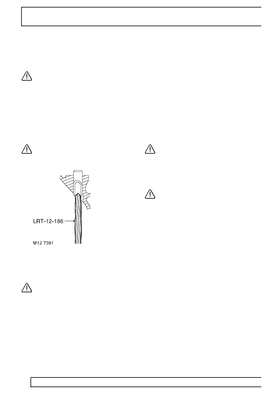
4. Remove carbon deposits from valve guides
using tool LRT-12-186.
CAUTION: Tool must be inserted from
combustion chamber face side of cylinder
head, ensure all loose particles of carbon
are removed on completion.
5. Check and record diameter of each valve stem.
Valve stem diameter:
Inlet = 6.907 to 6.923 mm (0.2719 to 0.2725 in)
Exhaust = 6.897 to 6.913 mm (0.2715 to 0.2721
in)
6. Renew any valve if stem diameter is less than
specified.
7. Check and record valve stem to guide clearance
using the following procedures:
8. Insert each valve into its respective guide.
9. Extend valve head 10 mm (0.375 in) out of valve
seat and position a DTI gauge to rear of valve
head.
10. Move valve towards front of cylinder head and
zero DTI gauge ensuring that stylus of gauge
remains in contact with valve head.
11. Move valve towards rear of cylinder head, record
gauge reading to give valve stem to guide
clearance.
Valve stem to guide clearance:
Inlet valve = 0.025 to 0.059 mm (0.0009 to
0.0023 in)
Exhaust valve = 0.035 to 0.069 mm (0.0013 to
0.0027 in)
CAUTION: If stem to guide clearance
exceeds figures given and valve stem
diameters were as specified, cylinder head
assembly must be replaced; it is not possible to
replace valve guides.
12. Repeat above procedures for remaining valves.
CAUTION: Keep valves in their fitted order.
13. Check face angle of each valve, renew any
valve with incorrect face angles, do not attempt
to recut.
Valve face angle:
Inlet = 29
°
48’
±
12’
Exhaust = 44
°
48’
±
12’