
L322 Range Rover System Description and Operation
AIR CONDITIONING
DESCRIPTION AND OPERATION
82-23
l
Maximum A/C Switch: For selection of maximum A/C when the ignition is on or rest heating when the ignition is
off. A LED above the switch is illuminated when maximum cooling or rest heating is selected.
l
Distribution Switches (Windscreen, Face and Footwell): For manual selection of air distribution in any
combination of windscreen, face and footwell outlets. A LED above each switch illuminates when a selection is
made.
l
Defrost Programme Switch: Activates a programme that automatically selects the windscreen heater on,
activates the compressor and changes the system settings to direct dry heat to the windscreen. A LED above
the switch is illuminated while the defrost programme is active.
l
Rear Window Heater Switch: Enabled only with the engine running. Pressing the switch energises the rear
window heater for a set time period, until the switch is pressed again or until the engine stops, whichever occurs
first. A LED above the switch is illuminated while the heater is on.
Inputs and Outputs
Five electrical connectors provide the interface between the ATC ECU and the vehicle/heater assembly wiring.
Both the low and high line systems receive ambient temperature, engine coolant temperature, engine speed and
vehicle speed inputs in K bus messages from the instrument pack. If the K bus messages are missing or faulty, the
ATC ECU adopts the following default values:
l
Ambient temperature = 0
°
C (32
°
F)
l
Engine coolant temperature = 80
°
C (176
°
F)
l
Engine speed = 800 rev/min
l
Vehicle speed = zero.
If a fault develops in the input from the temperature selector switch on the control panel, the ATC ECU adopts a default
value of 24
°
C (75
°
F).
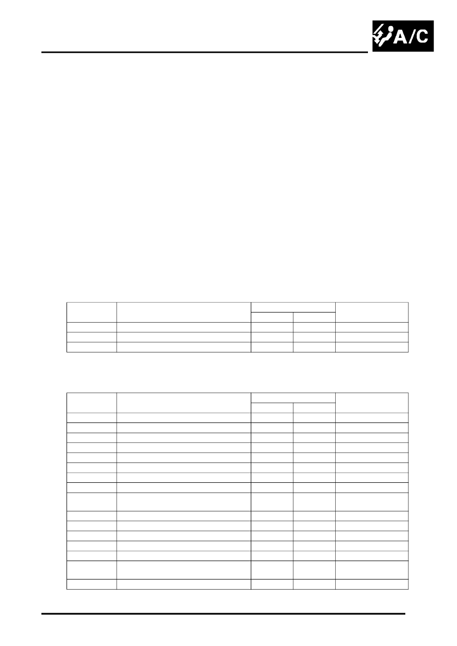
ATC ECU Harness Connector C0249 Pin Details
ATC ECU Harness Connector C0923 Pin Details
Pin No.
Description
System
Input/Output
Low
High
1
Front seat heating battery power supply
Yes
Yes
Input
2
LH front seat heater
Yes
Yes
Output
3
RH front seat heater
Yes
Yes
Output
Pin No.
Description
System
Input/Output
Low
High
1
Rear blower switch signal
No
Yes
Input
2
Rear blower switch power supply
No
Yes
Output
3
Automatic distribution switch
Yes
No
Input
4
LH heater matrix temperature sensor
No
Yes
Input
5
RH heater matrix temperature sensor
Yes
Yes
Input
6
Evaporator temperature sensor
Yes
Yes
Input
7
Blower control voltage
Yes
Yes
Output
8
Rear temperature switch
No
Yes
Input
9
Sensor ground (evaporator, and heater
temperature sensors)
Yes
Yes
–
10 to 12
Not used
–
–
–
13
Recirculation flap motor signal 2
Yes
Yes
Input
14
Recirculation flap motor signal 2
Yes
Yes
Output
15
Recirculation flap motor signal 1
Yes
Yes
Output
16
Recirculation flap motor signal 1
Yes
Yes
Input
17
Rear blower and temperature switch
power supply
No
Yes
Output
18
Not used
–
–
–