
Grand Voyager V6-201 3.3L VIN R SMFI (1997)
CAUTION: When installing the chassis brake tubes on the HCU valve block, they must be located correctly in the valve block to ensure proper
ABS operation. Refer to above image for the correct chassis brake tube locations.
NOTE: The chassis brake tube attachment locations to the HCU, are marked on the bottom of the HCU mounting bracket.
6. Install the 6 chassis brake tubes into their correct port locations on the HCU valve block as shown above. Tighten the tube nuts to a torque of 17
Nm (146 inch lbs.).
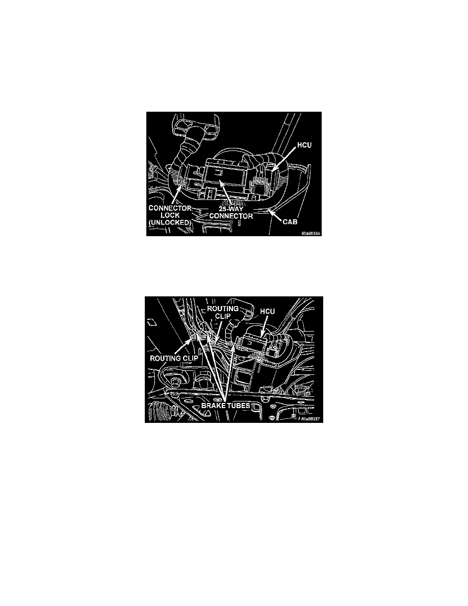
NOTE: Before installing the 25 way connector in the CAB be sure the seal is properly installed in the connector.
Unlocking CAB 25 Way Connector
7. Install the 25 way connector on the CAB using the following procedure. Position the 25 way connector in the socket of the CAB and carefully
push it down as far as possible. When connector is fully seated by hand into the CAB socket, push in the connector lock. This will pull the
connector into the socket of the CAB and lock it in the installed position.
Brake Tube Routing Clips
8. Install the routing clips on the brake tubes.
9. Lower vehicle.
10. Connect negative cable back on negative post of the battery.
11. Bleed the base brakes and the ABS brake hydraulic system.
See: Brakes and Traction Control/Brake Bleeding
12. Road test vehicle to ensure proper operation of the base and ABS brake systems.