
PB 150 V8-318 5.2L VIN T 2-BBL (1983)
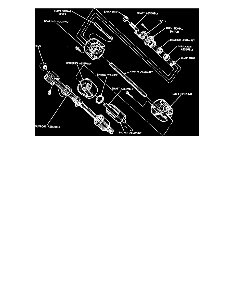
Fig. 8 Steering column exploded view. Motor Home
MOTOR HOME
Disassembly
1. Clamp column assembly in a vise.
2. Remove turn signal lever, then remove turn signal switch retaining screws and lift switch up and position aside.
3. Remove snap ring from upper end of steering shaft.
4. Remove the 3 bearing housing retaining screws. These screws must be removed before steering shaft is removed.
5. Install tool C-4044 or equivalent, and press shaft out of bearing, then remove bearing housing from shaft.
6. Remove bearing lower snap ring from shaft, then remove shaft through lower end of column.
7. Place ignition switch lock cylinder in Lock position and remove key. Insert a small screwdriver into lock cylinder release hole and push in to
release spring loaded lock retainer. Pull out lock cylinder and remove ignition switch.
8. Remove the 4 lock housing-to-column jacket hex head retaining screws and remove both housing and spring washer from jacket.
Inspection
1. Clean all parts in suitable cleaning solvent and inspect parts.
2. Inspect turn signal switch for distortion or broken parts or damaged parts. Inspect wiring harness for worn or bare spots.
3. Inspect steering shaft bearing for smooth operation. If bearing shows any signs of roughness or wear, it should be replaced.
Reassembly
1. Install boot and floor plate on lower end of column jacket.
2. Install spring washer and both housings.
3. Position ignition switch in center detent (Off) position. Feed wires down through the space between housing and jacket. Position switch in housing
and tighten the 3 retaining screws.
4. With ignition key cylinder in Lock position, remove key. Insert cylinder into housing, then press cylinder until contact is made with pin on ignition
switch cam. Insert key into lock and rotate until slot in cylinder plate aligns with pin. Press cylinder in the remaining way, making sure retainer bar
snaps into its slot in lock housing.
5. Insert steering shaft assembly into column, then install bearing lower snap ring on shaft.
6. Place rubber insulator with ground staple over column upper bearing and install assembly into housing bore. Use lubricant to ease installation.
7. Install turn signal switch, while feeding the wires through the opening in the housing, then install retaining plate and torque the 3 retaining screws
to 27 inch lbs.
8. Install turn signal lever and torque retaining screw to 30 inch lbs.
9. Place bearing housing assembly on column jacket assembly, while feeding wires through space between lower housing and jacket. Install wire
cover trough.
10. Using tool C-3879 or equivalent, washer and nut, install housing onto steering shaft. Remove tool and install snap ring.
11. Install the 3 bearing housing to lock housing screws and torque to 35 inch lbs.