seat Workshop Repair Guides

SEAT Workshop Service and Repair Manuals

Secondary shaft for 1st to 4th gear: adjustment > < Input shaft - Installation overview
Disassembly and assembly of the input shaft
Check the tool and equipment equivalence table according to the applicability between Seat / VW / Audi / Skoda → Chapter.
   
Special tools and workshop equipment required
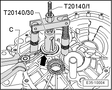
t  Extractor kit -T20140-, see equivalent → Anchor
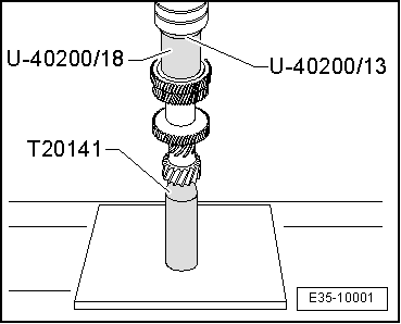
t  Hose clamp -T20141-, see equivalent → Anchor
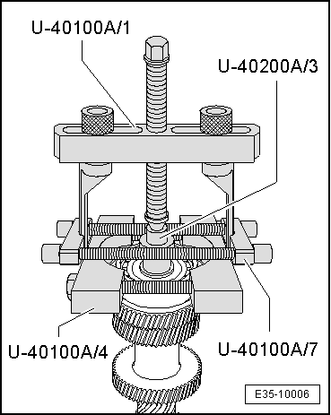
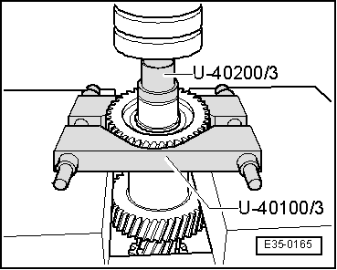
t  Extractor kit -U 40100B-, see equivalent → Anchor
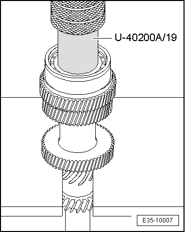
t  Kit (case) -U 40200A-, see equivalent → Anchor
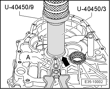
t  Kit (case) -U 40450A-, see equivalent → Anchor

   
Extract the ball bearing
–  Remove the input shaft securing ring.
–  Before fitting the bridge with bolt -U 40100/1- first fit the adaptor -U 40200/3- and the foot support flanges -U 40100/8- with the cone base -U 40100/4- to the input shaft.
  E35-10006
Release the 5thª gear pinion
–  Place the flat base -U 40100/3- under the pinion for the 5th gear
  E35-0165
Insert the 5thª gear pinion
–  Fit the input shaft in a vice with the pressure tool -T20141- and insert the adaptor -U 40200/13- tools and the adaptor -U 40200/18-.
  E35-10001
Insert the ball bearing
l  Installation position: the groove for the securing ring should point upwards and the rung should face towards the pinion of the 5th gear
–  Fit ball bearing with installation tool -U 40200/19-
–  Determine the securing ring → Fig. and fit it.
  E35-10007
Determining the correct securing ring
–  Fit a securing ring -A- of 1.86 mm in thickness in the groove of the input shaft and press upwards.
–  Measure clearance between grooved ball bearing -B- and fitted circlip -A- using feeler gauge -C-.
–  Remove the securing ring used for the measurement.
–  Select the securing ring according to the table; part number → Parts catalogue.
The following securing rings are used:
  N35-10005
Measured value (mm)Thickness of the securing ring (mm)Axial play (mm)
0,01 … 0,051,860,01 … 0,05
0,05 … 0,071,890,01 … 0,05
0,07 … 0,101,920,01 … 0,05
0,10 … 0,131,950,01 … 0,05
0,13 … 0,161,980,01 … 0,05

   
Extract the roller bearing from the clutch housing
–  To extract the roller bearings from the housing, press on the securing ring using a pliers.
–  Extract the bearing sockets using the adapter -T20140/1- and the pressure tool -T20140/30- .
  E35-10004
Extract the roller bearing from the clutch housing
–  When pressing the arrow -on the backup ring- tapered roller bearing with a -A- pair of pliers, squeeze the Adapter -U 40450/3- -U 40450/9-
–  Remove the pliers before leaving the roller bearing in installation position.
l  The securing ring should insert into the groove of the clutch pan.
  E35-10002

Secondary shaft for 1st to 4th gear: adjustment > < Input shaft - Installation overview