
Leon Mk1
|
|
|
|
|
|
|
|
|
|
|
|
|
|
|
|
|
|
|
 Note
Note
|
|
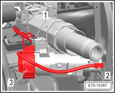
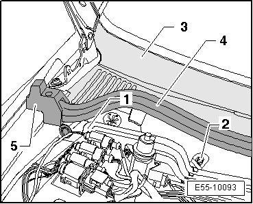
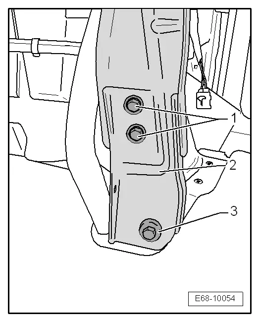
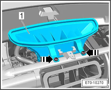
| – | Remove the rubber seal -2- of the grille under the windscreen -3-. |

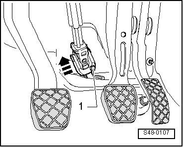
| – | Remove clips -1- fastening the grille below windscreen to the exterior upper sills. |
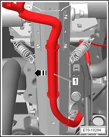
Note| The grille below the windscreen is inserted into a guide rail below the windscreen. |
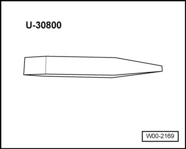
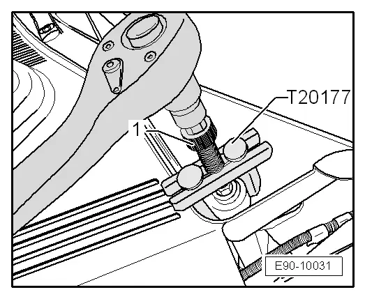
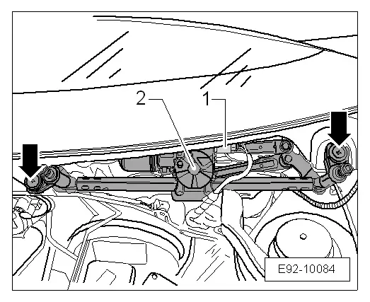
| – | Unhook the grille below the windscreen-2- from its mount in the windscreen cover using a llever -U30800-. |
| – | Remove the grille below the windscreen -2-. Pay particular attention that the wiper arm shafts are free. |
|
|
|
|
Note |
|
|
|
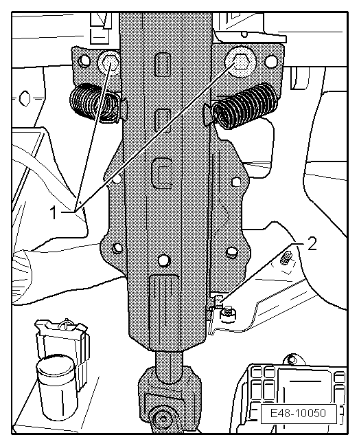
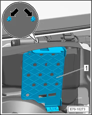
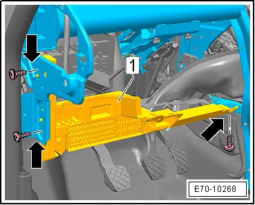
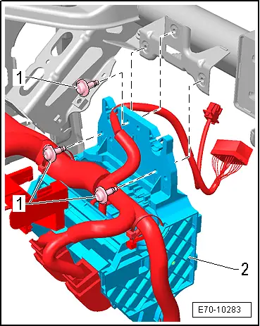
| – | Remove the staples -1- fastening the soundproofing trim. |

| – | Remove the soundproofing trim -2-on the plenum chamber. |
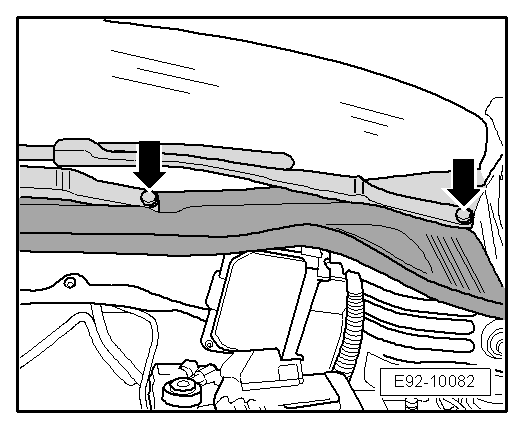
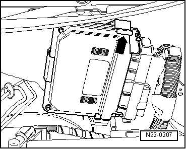
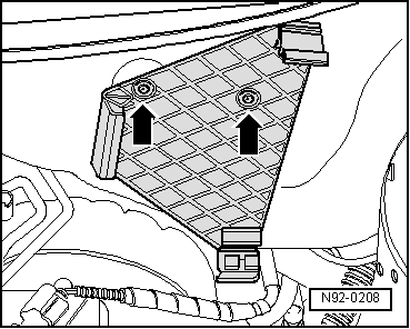
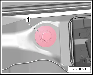
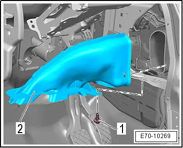
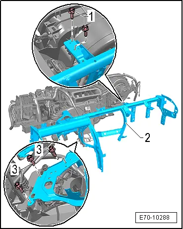
| – | Slacken bolts -1-. |

| – | Remove cover on water box -2-. |
|
|
|
|
|
|
|
|
|
|
|
|
|
|
|
|
|
|
|
|
|
|
Note
|
|