seat Workshop Repair Guides

SEAT Workshop Service and Repair Manuals

Components of the air conditioner - Automatic air conditioning (Climatronic) in the engine compartment > < Identification plates
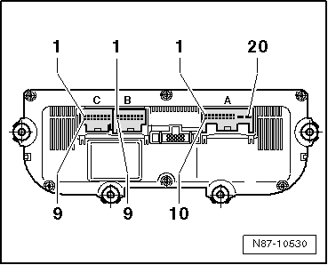
Plug connection of the Climatronic control unitJ255, vehicles 01.2004▶
Plug connection of the Climatronic control unit -J255-, vehicles 01.2004▶
For further information, see → Current flow diagrams, Electrical fault finding and Fitting locations.
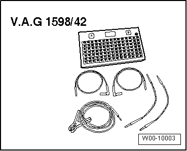
Special tools and workshop equipment required
t  Test box -V.A.G 1598/42-
   
t  Adapter cable -V.A.G 1598/47-
t  template -1598/47-2-
Pin assignment for multi-pin connectors A, B and C on back of Climatronic control unit -J255-
  W00-10003
20-pin connector, in the current circuit diagram T20c -A-
1 - Photosensor 2 for solar radiation -G134- or photosensor for solar radiation -G107-, signal
2 - High-pressure sender -G65-
3 - Photosensor 2 for solar radiation -G134- or photosensor for solar radiation -G107-, signal
4 - Cable control for VW (internal)
5 - Can High
6 - Can Low
7 - Cable control for VW (internal)
8 - Cable control for VW (internal)
9 - + 5V for photosensor 2 for solar radiation -G134- or photosensor for solar radiation -G107-
10 - Knurled knob to control the driver’s seat heating -E94- (optional)
11 - Knurled knob to control the passenger’s seat heating -E95- (optional)
12 - Terminal 15A
13 - Air temperature sender -G150-
14 - Air temperature sender, right vent -G151-
15 - Cable control for VW (internal)
16 - Terminal 30A
17 - Earth signal for sunlight penetration photosensor -G107-, sunlight penetration photosensor 2 -G134-, left vent temperature sender -G150- and right vent temperature sender -G151-.
18 - Air conditioning compressor control valve, air conditioning -N280-
19 - Terminal 31
20 - Terminal 30A; without supplementary heating terminal 15
  N87-10530
16-pin connector, in the current circuit diagram T16g -B-
1 - + 5V for servomotors
2 - Temperature flap control motor potentiometer -G220-
3 - Servomotor potentiometer for the right temperature flap -G221-
4 - Servomotor potentiometer for the de-icing flap -G135-
5 - Servomotor potentiometer for the central flap -G112-
6 - Servomotor potentiometer for the air recycling flap -G143-
7 - Potentiometer for air flow flap control motor -G113-
8 - Air temperature sender, foot well zone vent -G261-
9 - Air temperature sender, right footwell zone vent -G262-
10 - Fresh air intake duct temperature sensor -G89-
11 - air temperature sender, evaporator -G263-
12 - Cable control for VW (internal)
13 - Cable control for VW (internal)
14 - Potentiometer earth signal
15 - Cable control for VW (internal)
16 - Cable control for VW (internal)
  N87-10530
16-pin connector, in the current circuit diagram T16f -C-
1 - Temperature flap control motor -V158-, cold
2 - Temperature flap control motor -V158-, warm
3 - Servomotor for the de-icing flap -V107-, closed
4 - Servomotor for the de-icing flap -V107-, open
5 - Central flap control motor -V70-, direct vent
6 - Central flap control motor -V70-, footwell
7 - Air recirculation flap control motor -V113-, open
8 - Air recirculation flap control motor -V113-, closed
9 - Air flow flap control motor -V71-
10 - Air flow flap control motor -V71-
11 - Right temperature flap control motor -V159-, cold
12 - Right temperature flap control motor -V159-, warm
13 - Cable control for VW (internal)
14 - Cable control for VW (internal)
15 - Control unit for fresh air blower -J126-
16 - Control unit for fresh air blower -J126-, signal
  N87-10530

Components of the air conditioner - Automatic air conditioning (Climatronic) in the engine compartment > < Identification plates