seat Workshop Repair Guides

SEAT Workshop Service and Repair Manuals

Installing gearbox > < Gearbox, removing and fitting
Removing gearbox
Removing gearbox
  Note
t  Cleaning norms when working in the gearbox → Chapter.
t  General repair instructions. → Chapter
t  Observe notes on dual clutch gearbox (DSG) 02E → Chapter.
Removal:
  Note
All cable clamps that become loose or cut when removing must be re-installed in the same place when installing.
  Caution
Observe the measures to be adopted when disconnecting the battery → Rep. gr.27.
   
–  Switch ignition OFF.
–  Unplug electrical connector -1- from air mass meter - G70-.
–  Remove air hose -2-.
–  Screw out bolt -4- and detach air cleaner housing.
  Note
Possible disregarding of -item 3-.
–  Shift selector lever into position „P“.
–  Remove battery → Rep. gr.27.
  E34-10173
–  Remove battery tray -arrows-.
  A10-1572
–  Press the safety washer -A- upwards and remove by turning clockwise.
–  Press selector lever cable off selector shaft lever in -direction of arrow- and lift clear.
–  Do not loosen the bolt -B-.
–  Remove bolts -1-.
–  Do not bend or twist the selector lever cable.
  A37-0659
–  Unscrew earth connection -3-.
  Caution
The control unit (mechatronic unit) can be damaged by electrostatic discharge.
Do not touch contact pins in gearbox connector with bare hands.
–  Touch vehicle earth with your hand (without gloves) to discharge any static electricity.
–  Turn the electric connector -4- from the gearbox and remove it.
  Note
Disregard: -item 1, 2- and the -arrow-.
–  Remove starter → Rep. gr.27.
  A10-10607
–  Remove the connecting clip -1-
–  Throttle the gearbox oil line using the pressure tool - U 30042- and remove the line from the cooler -A-.
  E34-10165
–  Seal the radiator using a clean cap -1- from the Set - T20017A -.
  E34-10166
–  Unscrew all connecting bolts of the gearbox motor that can be reached from above (-10, 1, 3 and 5-).
  Note
Bolt -item 3- is located in aperture for starter.
  A34-10045
–  Unscrew the nuts -1- of the bracket on the front side of the gearbox oil sump -A-.
  E34-10167
–  Remove engine cover
  E15-10071
–  Fit the engine and gearbox support -U 30025E- on wing panel flanges and protect them against possible scratches.
–  Partly take up weight of engine with spindle, but do not lift.
  E13-10016
–  Unscrew bolts -1- and -2- and detach gearbox support -A-.
  A37-0653
–  Adjust the spindle of the support -U 30025E- to lower the gearbox to a dimension -a-.
l  Dimension -a- ± 120.
–  Remove the connection between the steering column and the steering box → Running gear; Rep. gr. 48
–  Raise the vehicle.
  E34-10166
–  Remove both front wheels.
–  Remove the noise insulation -1 and 3- → Rep. gr.50.
  A10-10761
–  Remove left sound insulation -Anchorage parts 1 ... 3-.
  A10-1566
–  Unbolt the exhaust system bracket -arrows-.
  A10-1632
–  Disconnect the connector -1- from the oil level and temperature sender -G266 -.
–  Lock subframe in position prior to removal → Running gear, front-wheel drive and four-wheel drive; Rep. gr. 40.
–  Remove subframe with pendulum support → Running gear, front-wheel drive and four-wheel drive; Rep. gr. 40.
  A10-10025
–  Unscrew the nuts -2- of the bracket on the front side of the gearbox oil sump -A-.
  E34-10167
–  Mark position of propshaft with flexible coupling in relation to bevel box flange.
–  Unscrew the cardan shaft with flexible disk from the pair of bevelled gears -arrows-.
  Note
When slackening off bolts, counterhold propshaft flange/final drive with a suitable lever.
  A10-10247
–  Press propshaft horizontally to rear as far as possible.
  Caution
t  When removing the gearbox, make sure the seal -arrow- on the cardan shaft flange is not damaged. Replace the cardan shaft if the seals are damaged.
t  Slackening off bolts for pendulum support/subframe causes engine/gearbox assembly to swing forwards slightly.
–  Press the unit to the front a little and separate the cardan shaft from the pair of bevelled gears.
–  Tie up the cardan shaft with a belt.
  V39-1817
–  Unscrew the insulating panel for the right half shaft from its mounting at the bevelled gears -arrows-.
–  Unbolt drive shafts (left and right) from gearbox flange shafts.
  E34-10168
–  Push the right and left articulated shafts forwards and fix to the longitudinal member -arrow- with a belt as illustrated in the figure.
  A10-1680
–  Unscrew bolts for gearbox carrier on bevel box -arrows 1- and engine -arrows 2-.
Do not remove gearbox carrier until gearbox has been pressed off engine.
  A34-10106
For removing the dual clutch gearbox (DSG) 02E for four-wheel drive, the gearbox support - T20138C- must be equipped with a bolt -3282/48-.
–  Take the fixing bolts from the bevelled gear on the gearbox -1- and replace with a type M10X55 for fixing the arm of the gearbox support -T20138C- to the bevelled gear.
–  Align the arm of the of the gearbox support in the direction of the borehole of the gearbox as show in the drawing.
  E34-10169
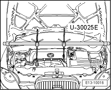
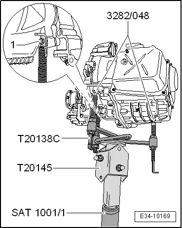
–  Attach the engine and gearbox jack -SAT 1040- and connect the base -T20145- under the vehicle using the hydraulic engine and gearbox jack adapter -SAT 1001/1-.
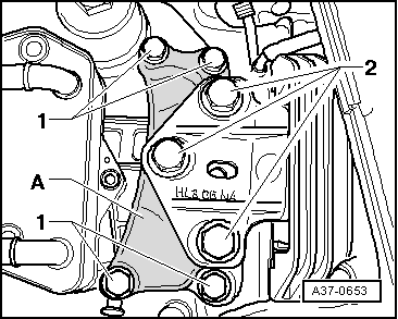
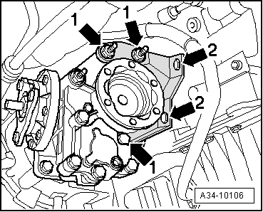
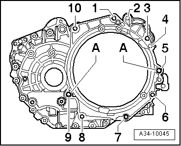
–  Unscrew the remaining connecting bolts of the gearbox motor -6, 7, 8 and 9-.
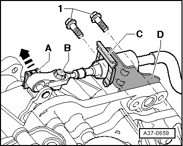
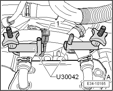
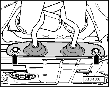
–  Remove the gearbox from the dowel sleeves -A-.
–  Pull the gearbox off engine first from the bevel box side and then from the front side.
–  Using the hydraulic jack -SAT 1040-, carefully lower the gearbox. in doing so, take care that no cables or lines catch anywhere.
  A34-10045

Installing gearbox > < Gearbox, removing and fitting