
Leon Mk2
| Driveshaft from year 2001 models onwards: repairing |

| Special tools and workshop equipment required |
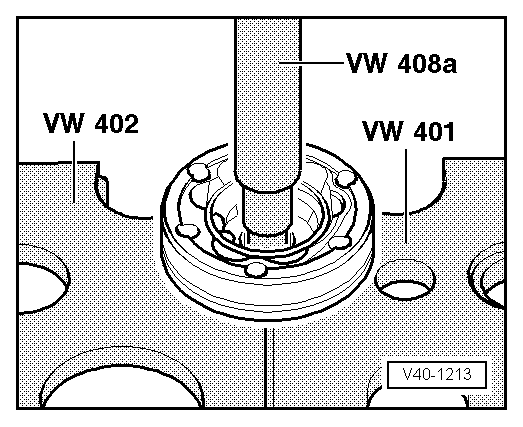
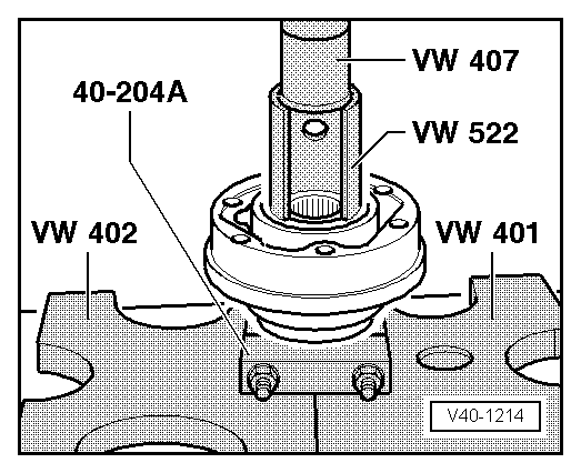
| t | Pressure plate -VW 401- |
| t | Pressure plate -VW 402- |
| t | Terminal crimper -VW 407- |
| t | Terminal crimper -VW 408 A- |
| t | Support sleeves -VW 522- |
| t | Tensor -40-204 A- |

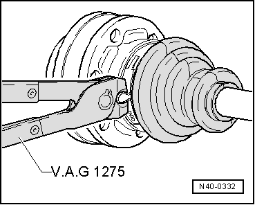
| t | Pliers -V.A.G 1275- |
| t | Torque wrench -V.A.G 1331- |
| t | Torque wrench -V.A.G 1332- |
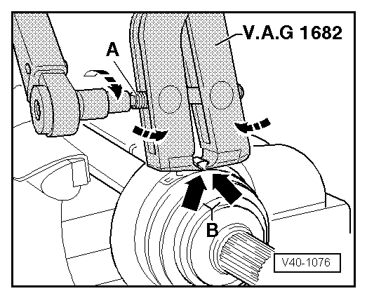
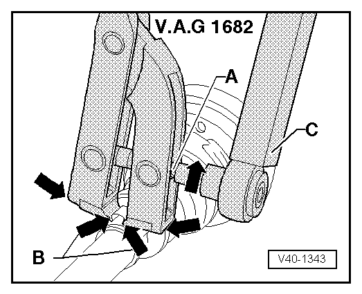
| t | Pliers -V.A.G 1682- |
|

| 1 - | Tightening clip |
| q | Replace |
| q | Tighten → Fig. |
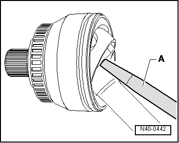
| 2 - | Constant velocity exterior joint |
| q | Only replace entirely |
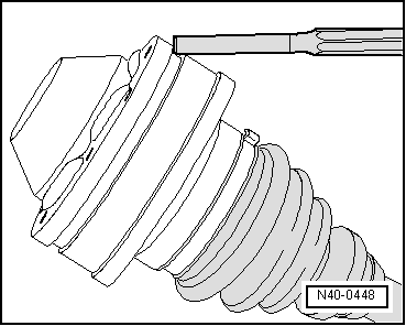
| q | Releasing → Fig. |
| q | Checking → Chapter |
| q | insert into the driveshaft using a plastic hammer, until the compressed circlip is decompressed |
| q | Grease → |
| 3 - | Hexagonal bolt |
| q | 150 Nm, and turn a further 90° |
| q | When tightening and loosening, the vehicle must rest on its wheels |
| q | Replace after each removal |
| 4 - | Driveshaft |
| 5 - | Circlip |
| q | Replace |
| q | Insert in the driveshaft groove |
| 6 - | Tightening clip |
| q | Replace |
| q | Tighten → Fig. |
| 7 - | Dust guard for constant velocity joint |
| q | Material: Hytrel (polyester elastomer) |
| q | Without ventilation opening |
| q | Check for cracks or wear, and replace if necessary |
| 8 - | Circlip |
| q | Replace |
| 9 - | Inner constant velocity joint |
| q | Only replace entirely |
| q | Releasing → Fig. |
| q | Checking → Chapter |
| q | Fitting → Fig. |
| q | The bonding surfaces must be free of grease and oil |
| q | Grease → |
| q | Insert and remove with long nose pliers |
| 10 - | Cover |
| q | Carefully remove using an awl |
| q | Apply D-3 on the seal surface before connecting it to the constant velocity joint |
| q | The bonding surface must be free of grease and oil! |
| 11 - | Tightening clip |
| q | Replace |
| q | Tighten → Fig. |
| 12 - | Dust guard of the inner constant velocity joint |
| q | With breather hole |
| q | Check for cracks or wear, and replace if necessary |
| q | Clean the driveshaft properly before fitting the new dust guard |
| q | Before fitting the dust guard, grease the driveshaft profile slightly |
| 13 - | Additional plate |
| 14 - | Bolt with internal splined head |
| q | First tighten diagonally to 10 Nm |
| q | Tighten completely to 70 Nm |
| q | Replace after each removal |
| 15 - | Cover |
| q | Carefully remove using an awl → Fig. |
| q | The bonding surface must be free of grease and oil! |
| q | Apply D-3 on the seal surface before connecting it to the constant velocity joint |
| 16 - | Seal |
| q | Replace, remove the protection layer and attach it to the joint. |
 Note
Note
|
|
|
|
|
|
|
|
|
|
Note
|
|