
Leon Mk2
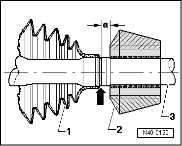
| Driveshaft: repairing |
| For vehicles with manual gearbox 006 and automatic gearbox 099 |

| Special tools and workshop equipment required |
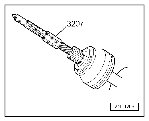
| t | Pressure spindle -3207- |
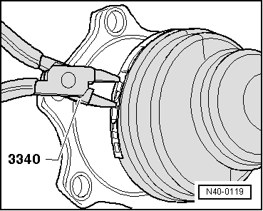
| t | Pliers -3340- |
| t | Pliers -V.A.G 1275- |
| t | Torque wrench -V.A.G 1331- |
| t | Torque wrench -V.A.G 1332- |
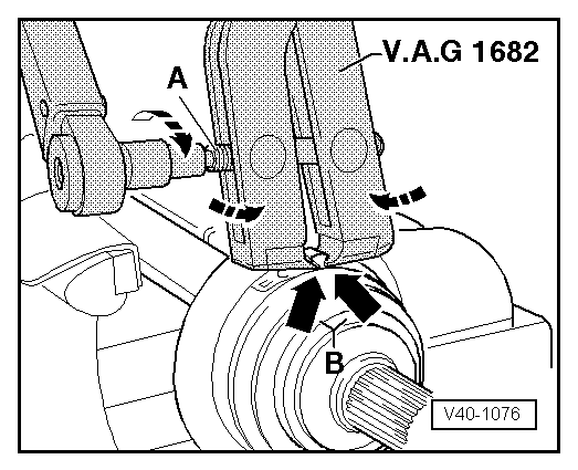
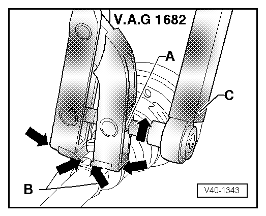
| t | Pincers -V.A.G 1682- |
|
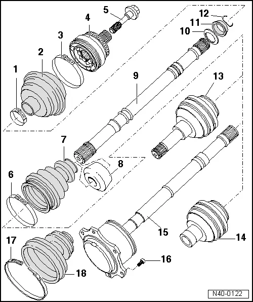
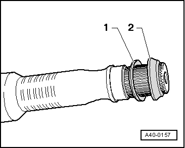
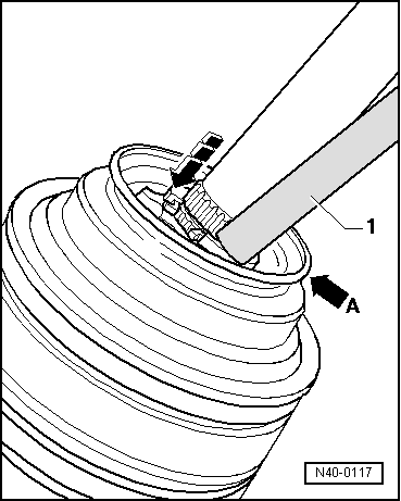
| 1 - | Tightening clip |
| q | Replace |
| q | Tighten → Fig. |
| 2 - | Dust guard for constant velocity joint |
| q | Check for cracks or wear, and replace if necessary |
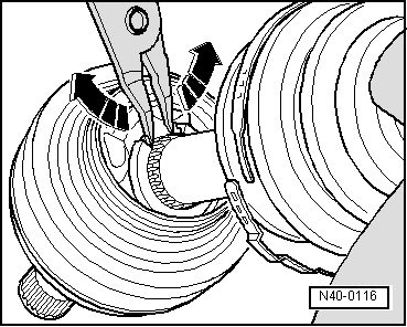
| 3 - | Tightening clip |
| q | Replace |
| q | Tighten → Fig. |
| 4 - | Constant velocity exterior joint |
| q | Only replace entirely |
| q | Releasing → Fig. |
| q | insert into the driveshaft using a plastic hammer, until the compressed circlip is decompressed |
| q | Grease → |
| q | Checking → Chapter |
| 5 - | Hexagonal bolt |
| q | 150 Nm, and turn a further 90° |
| q | Replace after each removal |
| 6 - | Tightening clip |
| q | Replace |
| q | Tighten with the -V.A.G 1275- |
| 7 - | Dust guard of the inner constant velocity joint |
| q | Check for cracks or wear, and replace if necessary |
| q | Clean the driveshaft properly before fitting the new dust guard |
| 8 - | Counterweight |
| q | Assembly position → Fig. |
| 9 - | Driveshaft |
| 10 - | Plate spring |
| q | Assembly position → Fig. |
| 11 - | Retaining ring |
| q | Assembly position → Fig. |
| 12 - | Circlip |
| q | Replace |
| q | Insert and remove with long nose pliers |
| 13 - | Left-hand side inner constant velocity joint |
| q | Only replace entirely |
| q | Releasing → Fig. |
| q | Grease → |
| q | Checking → Chapter |
| 14 - | Right-hand side inner constant velocity joint |
| q | Only replace entirely |
| q | Releasing → Fig. |
| q | Grease → |
| q | Checking → Chapter |
| 15 - | Driveshaft with inner joint (tripod) |
| q | Only vehicles with 4-cylinder engine and automatic gearbox |
| q | The inner joint cannot be repaired |
| q | Replace if damaged |
| 16 - | Allen bolt |
| q | First tighten diagonally to 10 Nm |
| q | Tighten completely to 70 Nm |
| q | Replace after each removal |
| 17 - | Tightening clip |
| q | Tighten → Fig. |
| 18 - | Dust guard of the inner constant velocity joint (tripod) |
| q | Only vehicles with 4-cylinder engine and automatic gearbox |
| q | Remove the outer constant velocity joint if the dust guard is to be replaced |
| q | Clean the driveshaft properly before fitting the new dust guard |
|
|
 Note
Note
|
|
|
|
|
|
|
|
|
|
|
|