seat Workshop Repair Guides

SEAT Workshop Service and Repair Manuals

Renewing bonded rubber bush for suspension link > < Removing and installing suspension link with mounting bracket
Removing and installing suspension link with mounting bracket (left side for vehicles with DSG or automatic gearboxes)
Special tools and workshop equipment required
   
t  Locking device -T10096-
  W00-1128
t  Engine/gearbox jack -V.A.G 1383 A-
Carry out the following work:
removing
–  Turn steering wheel to straight-ahead position and remove ignition key so that the steering lock engages.
Vehicles with keyless locking and starting system „Keyless Access“
–  Switch off ignition and open driver's door so that the steering lock engages.
Continued for all vehicles
  W00-0120
–  Unscrew nuts -arrows- and remove footwell trim.
  N48-10276
–  Unscrew bolt -arrow- from universal joint -1- and pull off universal joint in -direction of arrow-.
–  Loosen wheel bolts.
–  Raise the vehicle.
–  Remove front left wheel.
–  Remove lower noise insulation → General body repairs, exterior; Rep. gr.50.
  N48-10393
–  Detach exhaust system bracket from subframe -arrows-.
  M40-10010
–  Unscrew bolts -14- and detach pendulum support from gearbox.
–  If present, unscrew coupling rod of front left vehicle level sender -G78- from suspension link.
  N40-10341
–  Remove nuts -arrows-.
  N40-10188
–  Remove hexagon nut -1- from coupling rod -3- (left and right sides).
  N40-10382
–  Loosen bolt -12-.
–  Fit the subframe → Chapter.
  N40-10339
–  Place engine and gearbox jack -V.A.G 1383 A- under subframe.
–  Place, for example, a wooden block -1- between engine and gearbox jack -V.A.G 1383 A- and subframe.
  N40-10028
–  Remove bolts -13-.
  N40-10340
–  Remove bolts -9- and -10- and lower subframe as far as necessary.
  Note
Be sure to observe electrical wiring.
  N40-10338
–  Remove bolt -12- and remove suspension link from subframe.
Installation
Installation is carried out in reverse order. In the process, note the following:
  N40-10339
–  Always make sure that intermediate plate -1- is inserted between subframe -2- and body.
  Note
t  Ensure proper seating of dowel sleeves for steering box in suspension bracket.
t  Ensure that bellows are not damaged or twisted.
–  Install lower noise insulation → General body repairs, exterior; Rep. gr.50.
–  Mount the wheel and tighten to the bolts, tightening torque.
  N40-10546
Specified torques
ComponentTightening torque
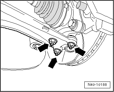
Suspension link to subframe
t  Use new bolts.
70 Nm + 180°
Swivel joint to cast steel suspension link
t  Use new nuts
60 Nm
Swivel joint to sheet steel or forged aluminium suspension link
t  Use new nuts
100 Nm
Mounting bracket to body
t  Use new bolts.
70 Nm + 180°
Mounting bracket to subframe
t  Use new bolts.
50 Nm + 90°
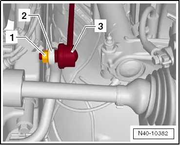
Anti-roll bar to subframe
t  Use new bolts.
20 Nm + 90°
Universal joint to steering box
t  Use new bolt.
30 Nm
Steering box to subframe
t  Use new bolts.
50 Nm + 90°
Exhaust system bracket to subframe
→ Engine; Rep. gr.26

   
Specified torques, subframe to body
Bolt.Tightening torque
M12 x 1.5 x 90
t  Use new bolts.
70 Nm and then turn 180° further
M12 x 1.5 x 100
t  Use new bolts.
70 Nm and then turn 180° further

   
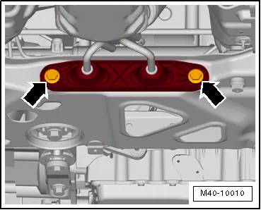
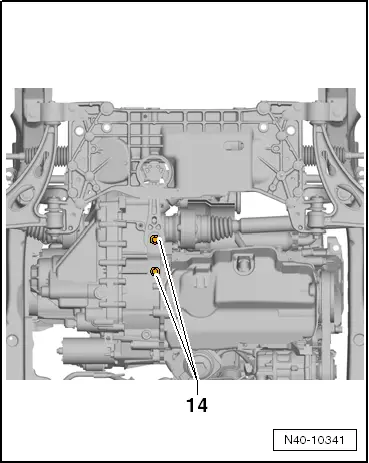
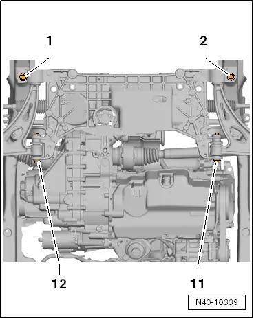
Specified torques for pendulum support to gearbox
Bolt.Tightening torque
M10 x 35
t  Use new bolt.
50 Nm and then turn 90° further
M10 x 75
t  Use new bolt.
50 Nm and then turn 90° further
M12 x 1.5 x 85 ; M12 x 1.5 x 50
t  Use new bolt.
60 Nm and then turn 90° further


Renewing bonded rubber bush for suspension link > < Removing and installing suspension link with mounting bracket