seat Workshop Repair Guides

SEAT Workshop Service and Repair Manuals

Assembly overview for the VL107 constant velocity slip joint > < Dismantling triple roller joint AAR?3300?i
Tripod type joint AAR 3300 i: assembly
Installation
–  Push up the dustguard on the drive shaft.
   
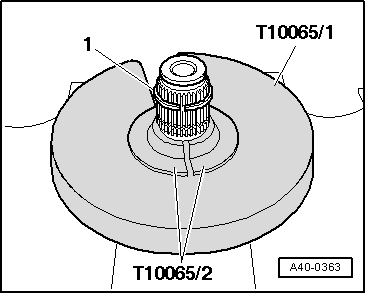
–  Press circlip -1- on as far as centre of splines.
  A40-0363
–  Use special tools as shown in the figure.
Depending on drive shaft version, assembly tool -T10065/3 - must be used instead of assembly tool -T10065/2 -.
Press triple roller spider onto drive shaft.
The bevel on the tripod should face the half shaft and it helps the fitting process.
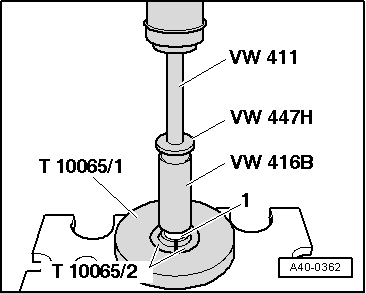
–  Fit triple roller spider onto shaft according to markings and drive home onto stop.
  A40-0362
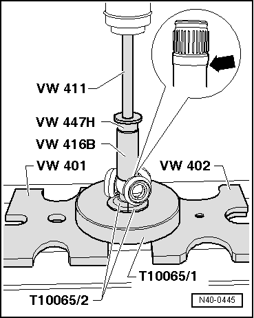
This figure is valid only for drive shafts with tapering end piece -arrow-!
–  Use the special tools shown in the illustration.
Special tool -T10065/2- must not come into contact with joint rollers.
  N40-0445
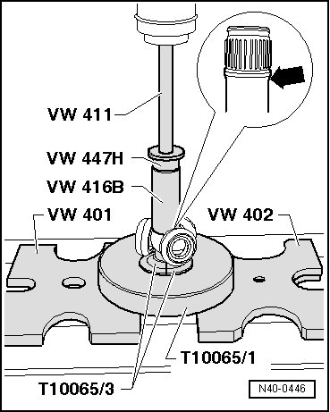
This description only applies to drive shafts with cylindrical end -arrow-.
–  Use the special tools shown in the illustration.
Special tool -T10065/3- must not come into contact with joint rollers.
–  Press triple roller spider onto drive shaft.
–  Circlip must engage audibly. Triple roller spider must lie directly against circlip (zero gap).
  N40-0446
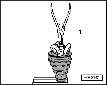
–  Install retaining ring.
1  - Circlip pliers (normal commercial type)
–  Press 70 g of drive shaft grease from the repair kit into the rear of the triple roller joint.
–  Lightly grease the rolling elements.
See that the rolling elements do not tilt to a side.
  A40-0357
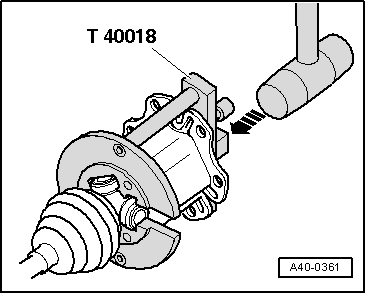
–  Adjust the joint on the tripod using a plastic hammer.
The illustration shows removal and assembly tool -T40018- for drive shaft AAR 3300 i.
–  Press in the remaining grease into the dustguard.
–  See that the bellow sits properly on the joint body.
–  Boot must rest in groove and on contour of joint body.
  A40-0361
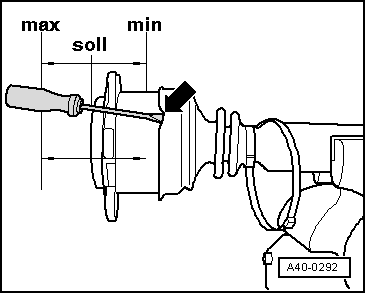
–  Position joint body in central position. See MIN / MAX positions
  Note
Use screwdriver or similar to vent air into boot while bringing joint body into centre position. -Arrow-
  A40-0292
–  Fit hose clip.
  Note
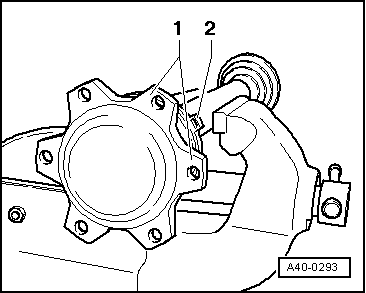
In order to be able to insert the internal multiple cog screw more easily in assembly, the binding lug -2- must be between the fastening flanges of the joint body-1-.
  A40-0293
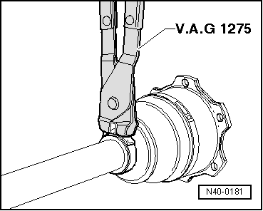
–  Tighten small hose clip with hose clip pliers - V.A.G 1275-.
  N40-0181

Assembly overview for the VL107 constant velocity slip joint > < Dismantling triple roller joint AAR?3300?i