
Leon Mk2
| Repairing drive shaft from model year 2001 |
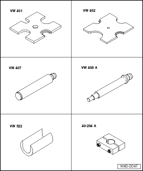
| Special tools and workshop equipment required |
| t | Press plate -VW 401- |
| t | Press plate -VW 402- |
| t | Press tool -VW 407- |
| t | Press tool -VW 408 A- |
| t | Support sleeve -VW 522- |
| t | Tensioner -40-204 A- |
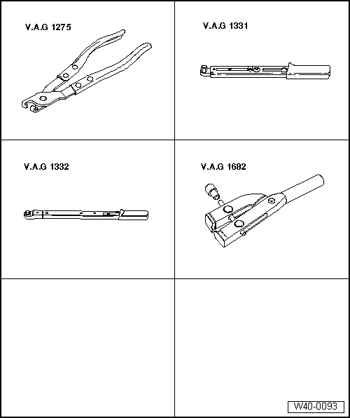
| t | Pliers -V.A.G 1275- |
| t | Torque wrench -V.A.G 1331- |
| t | Torque wrench -V.A.G 1332- |
| t | Pliers -V.A.G 1682- |
|
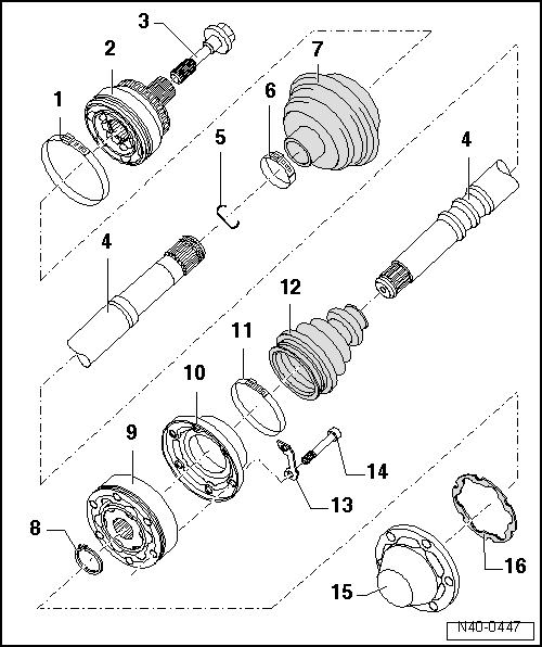
| 1 - | Clamp-type clip |
| q | Renew. |
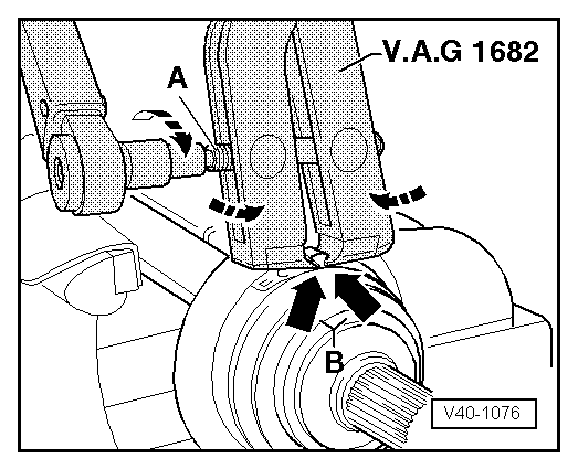
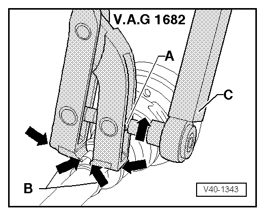
| q | Tensioning → Fig.. |
| 2 - | Outer constant velocity joint |
| q | Renew only complete. |
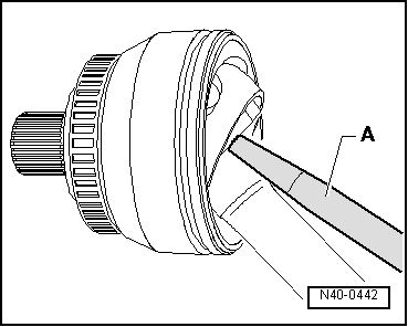
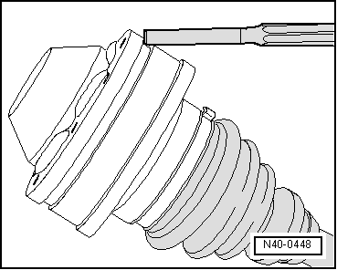
| q | Driving off → Fig.. |
| q | Checking → Chapter. |
| q | Installing: drive onto shaft with plastic hammer until compressed circlip seats. |
| q | Greasing → . |
| 3 - | Hexagon bolt |
| q | 150 Nm and turn 90° further. |
| q | The vehicle must be standing on the ground when loosening/tightening. |
| q | Renew each time after removing. |
| 4 - | Drive shaft |
| 5 - | Circlip |
| q | Renew. |
| q | Insert in shaft groove. |
| 6 - | Clamp-type clip |
| q | Renew. |
| q | Tensioning → Fig.. |
| 7 - | Bellows for outer constant velocity joint |
| q | Material: Hytrel (Polyelastomer). |
| q | No breather hole. |
| q | Check for tears and chafing, renew if necessary. |
| 8 - | Circlip |
| q | Renew. |
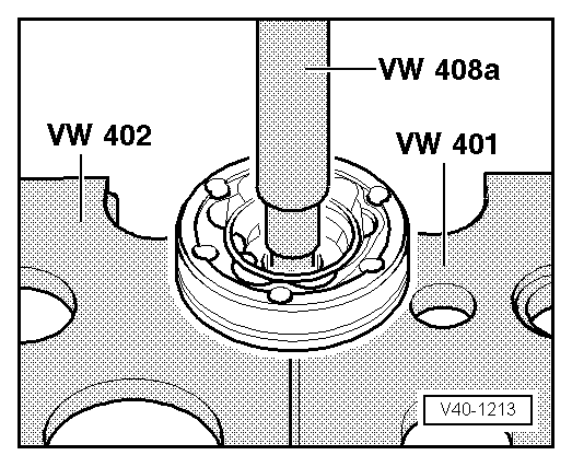
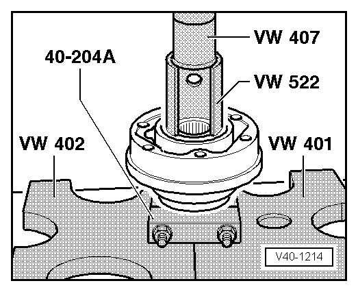
| 9 - | Inner constant velocity joint |
| q | Renew only complete. |
| q | Pressing off → Fig.. |
| q | Checking → Chapter. |
| q | Pressing on → Fig.. |
| q | Adhesive surface must be free of oil and grease. |
| q | Greasing → . |
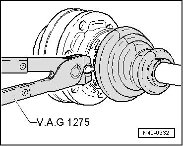
| q | Remove and install with long nosed pliers. |
| 10 - | Cap |
| q | Drive off with a drift. |
| q | Before fitting on constant velocity joint, coat sealing surface with D-3. |
| q | Adhesive surface must be free of oil and grease. |
| 11 - | Clamp-type clip |
| q | Renew. |
| q | Tensioning → Fig.. |
| 12 - | Bellows for inner constant velocity joint |
| q | With vent hole |
| q | Check for tears and chafing, renew if necessary. |
| q | Clean drive shaft thoroughly before installing new drive shaft bellows. |
| q | Lightly grease the drive shaft before installing the bellows. |
| 13 - | Locking plate |
| 14 - | Multi-point socket head bolt |
| q | Tighten using diagonal sequence to 10 Nm. |
| q | Tighten to 70 Nm. |
| q | Renew each time after removing. |
| 15 - | Cover |
| q | Drive off with a drift → Fig.. |
| q | Adhesive surface must be free of oil and grease. |
| q | Before fitting on constant velocity joint, coat sealing surface with D-3. |
| 16 - | Seal |
| q | Renew. Pull off protective foil and stick onto joint. |
 Note
Note
|
|
|
|
|
|
|
|
|
|
Note
|
|