skoda Workshop Repair Guides

Skoda Workshop Service and Repair Manuals

Removing and installing the console > < Release assembly carrier in the service position and align
Removing and installing the track control arm
Special tools and workshop equipment required
t  Multi-purpose tool -MP3-419 (VW 771)-
Removing:
  Note
Before commencing work, determine the measurement -a- → Chapter.
–  Remove front wheel.
–  Remove the sound dampening system → Body Work; Rep. gr.50.
–  Turn steering to right (remove left track control arm) or to the left (remove right track control arm).
  Note
When replacing the track control arm -2- or the ball joint -1- the installation position of the screws for the steering joint -arrows- to the track control arm and the installation position of the steering joint to the track control arm is not marked.
   
–  Mark fitting position of screws -arrows- from steering joint -1- to track control arm -2-.
–  Mark installation position of the steering joint -1- for the track control arm -2-.
–  Release screws -arrows-.
–  Pull the wheel-bearing housing with steering joint out of the track control arm.
  S40-0338
–  Release screw -1-.
  Note
Only swivel the track control arm as far as necessary out of the assembly carrier to avoid damaging the rubber-metal bearing.
–  Swivelling the track control arm -2- out of the assembly carrier.
  S40-0169
–  Pull out the track control arm -1- using the multi-purpose tool -MP3-419 (VW 771)- from the console.
  Note
When pulling out the track control arm ensure that the wheel house trim panel and the noise insulation are not damaged.
Installing:
–  Brush the track control arm studs with assembly sliding oil -G 294 421 A1-.
  Caution
t  When sliding in observe that the track control arm is in the correct installed position relative to the console. The surface of the track control arm must correspond with the surfaces in the console bearing → Chapter.
t  The track control arm should be flush with the assembly carrier.
t  If the fitting position is not respected, the rubber-metal bearing of the console may be damaged and its life may be shortened.
–  Insert the track control arm by hand into the rubber-metal bearing of the console, if necessary use a rubber hammer.
  S40-0333
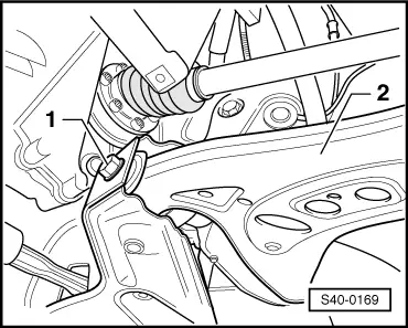
–  Insert the track control arm -2- in the assembly carrier, if necessary use a rubber hammer.
  Note
The tightening of the screw for steering joint and assembly carrier can be performed, if the dimension -a- is maintained (vehicle in unladen condition - unladen weight position) → Chapter.
–  Insert screw -1- and tighten to the former position/marking to a specified tightening torque.
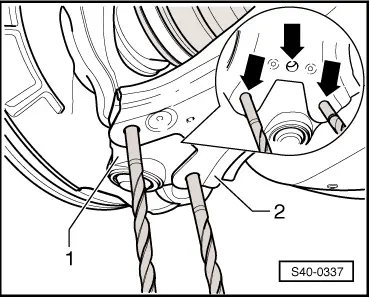
–  Insert steering joint in the track control arm.
–  If the track control arm is not replaced, tighten screws to former position/marking.
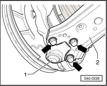
  Note
Use new screws and new lock washer to screw the steering joint/track control arm.
Vehicles on which the track control arm was replaced
  S40-0169
–  Position the track control arm -2- and steering joint -1- relatively to each other in such a way that the holes -arrows- of the track control arm and steering joint are flush.
For better fixing use two drifts with a Ø 8.3 mm or two drill bits also with a Ø 8.3 mm.
Continued for all vehicles
Further installation occurs in reverse order.
–  Install the noise insulation → Body Work; Rep. gr.50.
–  Installing and tightening the wheel → Chapter.
–  Perform chassis alignment → Chapter.
–  Perform a test drive.
  Caution
If after the test drive and with the front wheels pointing straight ahead the steering wheel is off straight, perform a chassis alignment → Chapter.
  S40-0337
Tightening torques:
Track control arm to assembly carrier
t  Use new screw!
t  Tighten in unladen weight position → Chapter.
70 Nm + 90°
Steering joint to track control arm
t  Use new screws!
t  Use new lock washer!
20 Nm + 90°
 
 
Wheel bolts120 Nm


Removing and installing the console > < Release assembly carrier in the service position and align