skoda Workshop Repair Guides

Skoda Workshop Service and Repair Manuals

Checking the charge-air system for leaktightness > < Removing and installing exhaust gas turbocharger
Checking charge pressure control
Special tools and workshop equipment required
t  
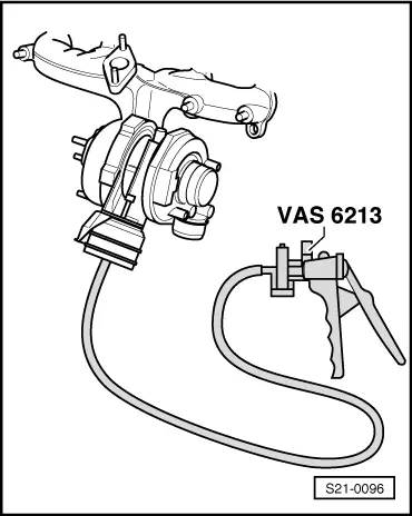
Hand vacuum pump, e.g. -V.A.S 6213-
t  Hand multimeter, e.g. -V.A.G 1715-
t  Vehicle system tester -V.A.G 1552-
t  Diagnostic cable -V.A.G 1551/3, 3A, 3B, 3C-
t  Measuring tool set, e.g. -V.A.G 1594 C-
t  Adapter cable -V.A.G 1598/31-
Test conditions
l  No fault in fault memory → 1.9/96 TDI Engine, Fuel Injection; Rep. Gr.01
l  No leaks on the intake and exhaust side
l  No fault on the engine/fuel injection system
l  Engine oil temperature at least 80 °C
Test sequence
If test and measuring devices are required during test drives observe the following:
  Note
t  Always secure the test and measuring devices on the rear seat and have a second person operate them there.
t  If the test and measuring equipment is operated from the front passenger seat, this can result in injuries to the persons sitting on that seat in the event of an accident which involves the front passenger airbag being deployed.
–  The charge pressure is measured with vehicle system tester -V.A.G 1552- when the engine is idling and during a road test.
–  Connect up the Vehicle system tester -V.A.G 1552- and select the address word 01 “Engine electronics” (the engine must be idling at the time) → 1.9/96 (TDI) Engine, Fuel Injection; Rep. Gr.01.
–  Select function 04“Initiate basic setting” and the display group 011.
   
Readout on display:
  Note
After selecting display group number 011, the idling speed is increased by the engine control unit in display block 1 to 1380...1420 rpm.
The display in display field 2 must switch between “off” and “on” every 10 seconds.
The following readouts must fluctuate in display fields 3 and 4:
Display field 2: off
t  Specification in display field 3: atmospheric pressure in mbar
t  Specification in display field 4: 98…100 %
Display field 2: on
t  Specification in display field 3: atmospheric pressure in mbar + 100...250 mbar
t  Specification in display field 4: 0…2 %
Continue the test as follows:
Press .
–  Select function 08“read measured value block” and display group 011.
–  Accelerate vehicle in 2nd gear from about 1000 rpm to 3200 rpm. While doing so the accelerator pedal must be fully pressed down.
 
Basic setting 11                      ->
1400 rpm     OFF      982 mbar      99 %
–  At about 3000 rpm read off the value indicated in display block.
Specification in display field 3: 2100…2600 mbar
If the specified value is not reached:
–  Conduct final control diagnosis for charge pressure control solenoid valve -N75- → 1.9ltr./96 (TDI) Engine, Fuel Injection; Rep. Gr.01.
The charge pressure control solenoid valve must operate for this test. While doing so the linkage of the charge pressure control vacuum unit at the bottom of the turbocharger must move back and forward. This linkage must move at least 3...4 times as long as a vacuum is present in the vacuum system.
If the linkage moves and the nominal charge pressure is not reached:
–  Replace turbocharger.
If the linkage does not move because the charge pressure control solenoid valve is not operating:
–  Inspect charge pressure control solenoid valve -N75- → 1.9/96 (TDI) Engine, Mechanics; Rep. Gr.23.
–  Inspect vacuum hoses → Chapter.
If the linkage does not move although the charge pressure control solenoid valve is operating:
 
Reading measured value block 11     ->
3090 rpm   2346 mbar   2281 mbar    6
–  Connect hand vacuum pump e.g. -V.A.S 6213- to charge pressure control valve and inspect linkage for unobstructed movement.
If the linkage only moves with difficulty or does not move at all:
–  Replace exhaust turbocharger → Chapter.
  S21-0096

Checking the charge-air system for leaktightness > < Removing and installing exhaust gas turbocharger