
Fabia Mk1
|
| Read measured value block 1 → | [lt ] Readout on display | ||||||
| xxx rpm | xx.x mg/s | x.xx °KW | xxx.x °C | ||||
| 1 | 2 | 3 | 4 | [lt ] Display field | Specification | Analysis | |
| Coolant temperature | 75.0 … 110.0 °C | --- | |||||
| Fuel delivery duration (set value) | 4...7 °KW 1) 5...8 °KW 2) | --- | |||||
| Injection rate | 3.0…9.0 mg/H | → Anchor | |||||
| Idling speed | 800…970 rpm | --- | |||||
| 1) for engine with identification characters AMF | |
| 2) for engine with identification characters BNM, BNV |
|
| Display -V.A.G 1552- | Rectifying fault | |||||
| below 3.0 mg/s |
| |||||
| above 9.0 mg/s |
| |||||
|
| Read measured value block 2 → | [lt ] Readout on display | ||||||
| xxx rpm | xxx.x % | x x x | xxx.x °C | ||||
| 1 | 2 | 3 | 4 | [lt ] Display field | Specification | Analysis | |
| Coolant temperature | 75.0 …110.0 °C | --- | |||||
| Operating position | 1 1 0 | → Anchor | |||||
| Accelerator pedal position | 0,0 % | → Anchor | |||||
| Idling speed | --- | → Anchor | |||||
|
| Display -V.A.G 1552- | Rectifying fault | |||
| 1…100,0 % |
| |||
|
| Meaning, if display positions = 1 | ||||
| X | X | X | Operating position | |
| 1 | Air conditioning switched on | |||
| 1 | Idling switch closed (accelerator pedal not pressed) | |||
| 1 | Ignore | |||
|
| Read measured value block 3 → | [lt ] Readout on display | ||||||
| xxx rpm | xxx mg/s | xxx mg/s | xxx % | ||||
| 1 | 2 | 3 | 4 | [lt ] Display field | Specification | Analysis | |
| On/off ratio (actuation) of exhaust gas recirculation valve | 30…80 % | --- | |||||
| drawn in air mass (actual) | 258...410 mg/H 1) 230...370 mg/H 2) | → Anchor | |||||
| drawn in air mass (nominal) | 278...390 mg/H 1) 230...360 mg/H 2) | → Anchor | |||||
| Idling speed | --- | → Anchor | |||||
| 1) for engine with identification characters AMF | |
| 2) for engine with identification characters BNM, BNV |
|
| Display -V.A.G 1552- | Rectifying fault | |||
| above 390 mg/H 1) above 360 mg/H 2) |
| |||
| 1) for engine with identification characters AMF | |
| 2) for engine with identification characters BNM, BNV |
|
| Display -V.A.G 1552- | Rectifying fault | |||||||
| above 258 mg/H 1) above 230 mg/H 2) |
| |||||||
| above 410 mg/H 1) above 370 mg/H 2) |
| |||||||
| 1) for engine with identification characters AMF | |
| 2) for engine with identification characters BNM, BNV |
|
| Read measured value block 4 → | [lt ] Readout on display | ||||||
| xxx rpm | xx.x ° b. TDC | xx.x °KW | xx.x °KW | ||||
| 1 | 2 | 3 | 4 | [lt ] Display field | Specification | Analysis | |
| Synchronizing angle | -3...+3 °CA | → Anchor | |||||
| Fuel delivery duration (set value) | 4,0...7,0 °CA 1) 5...8 °CA 2) | --- | |||||
| Commencement of injection (set value) | 3…9° BTDC 1) 0…4° v. BTDC 2) | → Anchor | |||||
| Idling speed | --- | → Anchor | |||||
| 1) for engine with identification characters AMF | |
| 2) for engine with identification characters BNM, BNV |
|
| Display -V.A.G 1552- | Rectifying fault | |||
| less than 3° BTDC 1) less than 0° BTDC 2) |
| |||
| 1) for engine with identification characters AMF | |
| 2) for engine with identification characters BNM, BNV |
|
| Display -V.A.G 1552- | Rectifying fault | |||||
| above 3°KW or under -3°KW |
| |||||
|
| Read measured value block 5 → | [lt ] Readout on display | ||||||
| xxx rpm | xx.x mg/s | xx.x ° b. (n.) TDC | xxx.x °C | ||||
| 1 | 2 | 3 | 4 | [lt ] Display field | Specification | Analysis | |
| Coolant temperature | 75…110 °C | --- | |||||
| Synchronisation when starting | 1 | --- | |||||
| drawn in air mass when starting | 9…15 mg/H | --- | |||||
| Idling speed | --- | → Anchor | |||||
|
| Read measured value block 6 → | [lt ] Readout on display | ||||||
| xxx km/h | xxx | xx.x % | xxx | ||||
| 1 | 2 | 3 | 4 | [lt ] Display field | Specification | Analysis | |
| Operating condition of the cruise control system | xxx | → Anchor | |||||
| Accelerator pedal position | 0 % | → Anchor | |||||
| Status of the brake and clutch pedal switch | 000 | → Anchor | |||||
| Vehicle speed | 0 km/h | --- | |||||
|
| Meaning, if display positions = 1 | ||||
| X | X | X | Operating position | |
| 1 | Brake light switch -F- closed (brake pedal operated) | |||
| 1 | Brake pedal switch -F47- opened (brake pedal operated) | |||
| 1 | Clutch pedal switch -F36- opened (clutch pedal operated) | |||
|
| Display | Operating position | |
| 0 | Vehicles with activated cruise control system, switch in position “OFF” | |
| 1 | Vehicles with activated cruise control system, switch in position “ON” | |
| 255 | Vehicle without cruise control system or cruise control system function in engine control unit not activated | |
|
| Read measured value block 7 → | [lt ] Readout on display | ||||||
| xxx.x °C | xxx % | xxx.x °C | xxx.x °C | ||||
| 1 | 2 | 3 | 4 | [lt ] Display field | Specification | Analysis | |
| Coolant temperature | approx. ambient temperature 1) | → Anchor | |||||
| Intake manifold temperature | approx. ambient temperature 1) | → Anchor | |||||
| Status of the fuel cooling | 0 % | --- | |||||
| Fuel temperature | approx. ambient temperature 1) | → Anchor | |||||
| 1) It is not possible to give a nominal value indication for temperatures. Once the engine has cooled down the temperatures of the fuel, intake manifold and coolant must approximately correspond with the ambient temperature. If there is a marked value difference check the relevant sender. |
|
| Display -V.A.G 1552- | Rectifying fault | |||
| 40.5 °C |
| |||
|
| Display -V.A.G 1552- | Rectifying fault | |||
| approx. 135.9 °C |
| |||
|
| Display -V.A.G 1552- | Rectifying fault | |||
| -5.4 °C |
| |||
|
| Read measured value block 10 → | [lt ] Readout on display | ||||||
| xxx mg/s | xxxx mbar | xxxx mbar | xxx % | ||||
| 1 | 2 | 3 | 4 | [lt ] Display field | Specification | Analysis | |
| Accelerator pedal position | 0,0 % | → Anchor | |||||
| Charge pressure (actual) | 900...1150 mbar | --- | |||||
| Atmospheric pressure | 900...1100 mbar | --- | |||||
| drawn in air mass (actual) | 258...410 mg/H 1) 230...360 mg/H 2) | → Anchor | |||||
| 1) for engine with identification characters AMF | |
| 2) for engine with identification characters BNM, BNV |
|
| Read measured value block 11 → | [lt ] Readout on display | ||||||
| xxx rpm | xxxx mbar | xxxx mbar | xx % | ||||
| 1 | 2 | 3 | 4 | [lt ] Display field | Specification | Analysis | |
| On/off ratio (actuation) of solenoid valve for charge pressure control -N75- | 25…95 % | --- | |||||
| Charge pressure (actual) | 900…1150 mbar | --- | |||||
| Charge pressure (nominal) | 900…1100 mbar | --- | |||||
| Idling speed | --- | → Anchor | |||||
|
| Read measured value block 13 → | [lt ] Readout on display | ||||||
| x.xx mg/s | x.xx mg/s | x.xx mg/s | |||||
| 1 | 2 | 3 | 4 | [lt ] Display field | Specification | Analysis | |
| Smooth running control - injected quantity cylinder 3 | -3…+3 mg/H 1) -2.8…+2.8 mg/H 2) | → Anchor | |||||
| Smooth running control - injected quantity cylinder 2 | -3…+3 mg/H 1) -2.8…+2.8 mg/H 2) | → Anchor | |||||
| Smooth running control - injected quantity cylinder 1 | -3…+3 mg/H 1) -2.8…+2.8 mg/H 2) | → Anchor | |||||
| 1) for engine with identification characters AMF | |
| 2) for engine with identification characters BNM, BNV |
|
| Read measured value block 16 → | [lt ] Readout on display | ||||||
| xxx % | xxxxxxxx | xx | xx.x V | ||||
| 1 | 2 | 3 | 4 | [lt ] Display field | Specification | Analysis | |
| Supply voltage of the engine control unit | 13.5…14.5 V | → Anchor | |||||
| Heating element control | xx | → Anchor | |||||
| Auxiliary heating | 1x000001 | → Anchor | |||||
| Generator capacity | 5…95 % | --- | |||||
|
| Meaning, if display positions = 1 | |||||||||
| X | X | X | X | X | X | X | X | Additional heating deactivated, because: | |
| 1 | Coolant temperature greater than 70...80°C or intake air temperature greater than +5°C | ||||||||
| 1 | Generator defective | ||||||||
| 1 | Battery voltage below 9 V | ||||||||
| 1 | Engine speed less than 800 rpm | ||||||||
| 1 | Engine start within the last 10 seconds | ||||||||
| 1 | Coolant temperature sender -G62- or Intake manifold temperature sender -G72- defective | ||||||||
| 1 | do not observe 1) / additional heating Zusatzbeheizungsforderung 2) | ||||||||
| 1 | Ignore | ||||||||
| 1) for engine with identification characters AMF | |
| 2) for engine with identification characters BNM, BNV |
|
| Meaning, if display positions = 1 | |||
| X | X | Operating position | |
| 1 | Low heat output relay -J359- on | ||
| 1 | High heat output relay -J360- on | ||
|
| Display -V.A.G 1552- | Rectifying fault | |||||||||
| below 13.5 V |
| |||||||||
| above 14.5 V |
| |||||||||
|
| Read measured value block 18 → | [lt ] Readout on display | ||||||
| xx | xx | xx | xx | ||||
| 1 | 2 | 3 | 4 | [lt ] Display field | Specification | Analysis | |
| Ignore | |||||||
| Unit injector solenoid valve cyl. 3 | 0 | → Anchor | |||||
| Unit injector solenoid valve cyl. 2 | 0 | → Anchor | |||||
| Unit injector solenoid valve cyl. 1 | 0 | → Anchor | |||||
|
| Display -V.A.G 1552- | Rectifying fault | |||||
| If number instead of zero |
| |||||
|
| Read measured value block 22 → | [lt ] Readout on display | ||||||
| x | xxxxxx | x | x | ||||
| 1 | 2 | 3 | 4 | [lt ] Display fields | Specification | Analysis | |
| Operating state of air conditioning | 0 | — | |||||
| Operating state of charge pressure control | 0 | — | |||||
| Operating state of cruise control | xxxxxx | → Anchor | |||||
| Operating condition of the cruise control system | x | → Anchor | |||||
|
| Operating condition of the cruise control system | ||||
| 0 | Vehicle without CCS, or CCS function in engine control unit not activated | |||
| 1 | Vehicles with activated CCS, switch in position “OFF” | |||
| 9 | Vehicles with activated CCS, switch in position “ON” | |||
|
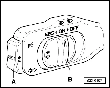
|
| Cruise control | Display field 2 |
| Switch B on “ON” | 000011 |
| Switch B on “RES” | 001011 |
| Switch A operated | 000111 |
| Switch B to “OFF” before operating point | 000001 |
| Switch B to “OFF” locked | 000000 |