
Fabia Mk1
| Fuel tank with component parts - Summary of components |
 Note
Note| t | Fuel lines are secured with quick-release fittings. |
| t | Fuel hoses in the engine and fuel filter must only be secured with spring strap clamps. The use of clamp-type or screw-type clips is not allowed. |
| t | Observe safety measures → Chapter. |
| t | Observe rules for cleanliness → Chapter. |
| Repairing the accelerator control → Chapter |
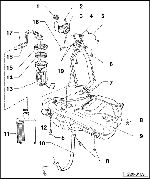
| 1 - | Cap |
| 2 - | 1.5 Nm |
| 3 - | Fuel tank lid unit |
| q | with rubber bowl |
| 4 - | Gravity valve |
| q | to remove, unclip valve at top and lift out of filler neck. |
| q | inspect valve for blockage: |
| t | valve vertical: Valve open |
| t | valve tilted 45°: Valve closed |
| 5 - | Earth connection |
| 6 - | 10 Nm |
| 7 - | Vent lines |
| q | clipped in place on fuel tank |
| 8 - | 25 Nm |
| 9 - | Fuel tank |
| q | when removing support, for example with the engine/gearbox jack -V.A.G 1383 A - |
| q | removing and installing → Chapter |
| 10 - | Tensioning strap |
| 11 - | Fuel cooler |
| q | removing and installing → Chapter |
| 12 - | 20 Nm |
| 13 - | Fuel pump/sender unit for fuel gauge display |
| q | for vehicles ► 04.00: Sender unit for fuel gauge display |
| q | for vehicles 05.00 ►: Fuel pump with sender unit for fuel gauge display |
| q | removing and installing → Chapter |
| q | removing and installing fuel gauge sensor → Chapter |
| 14 - | Gasket ring |
| q | replace if damaged |
| q | moisten with fuel before installing |
| 15 - | Union nut |
| q | use wrench -MP 1-227- for removing and installing |
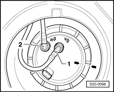
| 16 - | Feed line |
| q | to fuel filter → Chapter |
| q | on connection with identification -V- (flange) |
| q | black |
| q | to remove from connecting flange press release button |
| q | check for firm seating |
| q | clipped in place on fuel tank |
| 17 - | Return-flow line |
| q | from fuel cooler → Chapter |
| q | on connection with identification -R- (flange) |
| q | blue |
| q | to remove from connecting flange press release button |
| q | check for firm seating |
| q | clipped in place on fuel tank |
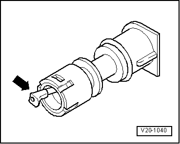
| 18 - | Vent valve |
| q | to remove, unclip valve at side and take out of filler neck. |
| q | before installing, unscrew cap |
| q | check → Fig. |
| 19 - | O-ring |
| q | replace |
Note
|
|