skoda Workshop Repair Guides

Skoda Workshop Service and Repair Manuals

Electric/electronic components of the gearbox > < Vehicle components
Fitting locations
Fitting locations
   
Engine control unit
Fitting location: The control unit is located at bulkhead.
Removing and installing the control unit → Engine, Fuel Injection; Rep. Gr.24
  S24-0373
Diagnostic connection
Fitting location: The diagnostic connector is located behind the storage area -arrow- on the driver's side.
  S01-0104
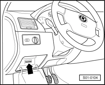
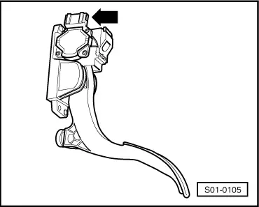
Accelerator pedal position sender -G79-
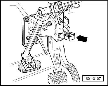
Fitting location: The accelerator pedal position sender - G79--arrow- is a component part of the gas pedal.
The accelerator pedal position sender -G79- generates the “Kick-down signal”, when the accelerator pedal is suddenly pressed down fully.
For self-diagnosis
Signal can only be checked in the measured value block → Chapter.
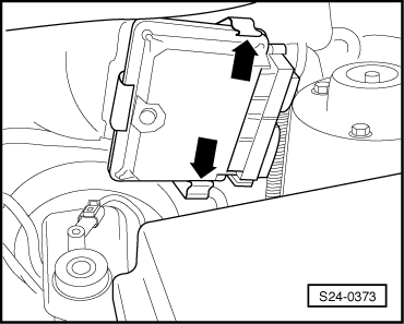
Removing and installing accelerator pedal position sender -G79 -
→ Engine, Mechanics; Rep. Gr.20
  S01-0105
Brake light switch -F-
Fitting location: The brake light switch -F--arrow- is located in the foot controls.
For self-diagnosis
Signal can be checked in the measured value block → Chapter.
Removing and installing the brake light switch
→ Chassis; Rep. Gr.45
  S01-0107
Relay for starter interlock switch -J207-
Fitting location: The relay is located on the relay carrier -1- above the vehicle voltage control unit -2-.
The relay carrier is located behind the storage area on the driver's side.
The relay is identified by the number “53”.
Removing and installing the relay
–  Remove the storage area on the driver's side → Body Work; Rep. Gr.68.
–  Remove the relay from the relay carrier.
  S01-0108
Automatic Gearbox Control Unit -J217-
The control unit -arrow- is located behind the battery on the battery tray.
Removing the control unit
–  Switch off ignition, open engine compartment cover.
–  Unlock the multi-pin connector and unplug it from the control unit.
  S01-0111
–  Release the two screws -arrows- and remove the control unit.
Installation is carried out in the reverse order.
–  Initiate basic setting → Chapter.
–  Perform the self-diagnosis → Chapter.
  S01-0109
Gear selector lever position indicator -Y6-
Fitting location: in the dash panel insert
Removing and installing: → Electrical System; Rep. Gr.90
For self-diagnosis:
In the event of emergency running mode and if the control unit is operational all segments of the selector lever position indicator -Y6- light up in the dash panel insert.
In the event of emergency running mode and if the control unit fails there is no indication of the selector lever positions.
  S01-0103

Electric/electronic components of the gearbox > < Vehicle components