
Fabia Mk1
| Control cables up to 05.06 |
 Note
Note| Grease bearing and friction surfaces with grease -G 000 450 02-. |

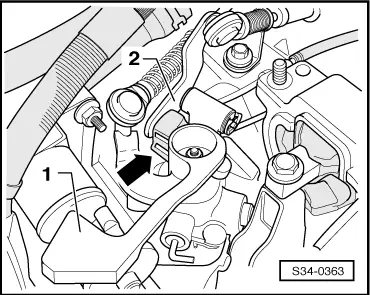
| 1 - | Shift cable |
| q | press onto shift lever guide |
| q | Fitting position → Chapter |
| 2 - | Selector cable |
| q | at selector angle plate |
| q | Fitting position → Chapter |
| 3 - | Lock washer |
| q | replace → Electronic Catalogue of Original Parts |
| 4 - | Lock washer |
| q | do not damage cables when removing |
| q | replace → Electronic Catalogue of Original Parts |
| 5 - | Shift housing |
| 6 - | Cable support |
| 7 - | Grommet |
| q | for mounting of cable support to gearbox |
| 8 - | Spacer |
| 9 - | 23 Nm |
| q | 3 pieces |
| q | for cable support |
| 10 - | Cable lock |
| q | for selector cable Pos.2 at relay lever Pos.14 |
| q | up to 10.04 - after removing from relay lever always replace → Electronic Catalogue of Original Parts |
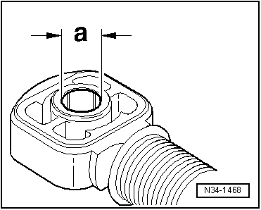
| q | as of 11.04 with bored through holes; must no longer be replaced → Fig. |
| q | is fixed with a circlip |
| q | after installing set shift mechanism → Chapter |
| 11 - | Cable lock |
| q | for shift cable Pos.1 at gearshift lever Pos.16 |
| q | up to 10.04 - after removing from gearshift lever always replace → Electronic Catalogue of Original Parts |
| q | as of 11.04 with bored through holes; must no longer be replaced → Fig. |
| q | is fixed with a circlip |
| q | after installing set shift mechanism → Chapter |
| 12 - | Lock washer |
| q | replace → Electronic Catalogue of Original Parts |
| 13 - | Bushing |
| 14 - | Reversing lever |
| q | Fitting position → Fig. |
| 15 - | Sliding shoe |
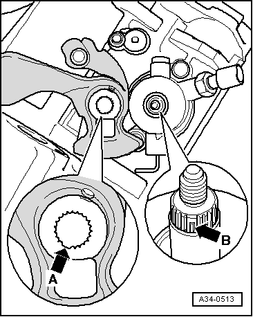
| 16 - | Gearshift lever |
| q | with balancing weight |
| q | insert in such a way that the interrupted spacing of the teeth matches the gearshift shaft → Fig. |
| q | after installing set shift mechanism → Chapter |
| q | Fitting position → Fig. |
| 17 - | 20 Nm |
| q | replace → Electronic Catalogue of Original Parts |
|
|
|
|
| Cable lock for: | Dimension “a” |
| Shift cable at gearbox shift lever | 10 mm |
| Selector cable at relay lever | 8 mm |