skoda Workshop Repair Guides

Skoda Workshop Service and Repair Manuals

Engine cooling > < Balancing shaft and retaining frame - Summary of components
removing and installing balancing shaft
Special tools and workshop equipment required
t  Locking pin -T10060A-
t  Socket insert XZN 14 -T10061-
Removing
–  Removing toothed belt → Chapter.
–  Removing the oil pan → Chapter.
–  Remove the sealing flange on the belt pulley side → Chapter.
–  Unscrew fixing screws for cover.
–  Remove the cover from the retaining frame.
   
–  Lock chain tensioner with locking pin -T10060A--arrow-.
–  Unscrew chain sprocket for guide pulley -1- from retaining frame.
–  Unscrew fixing screws -2- from the chain tensioner and remove chain tensioner.
–  Remove chain from chain sprockets and place on a clean surface.
  N13-0539
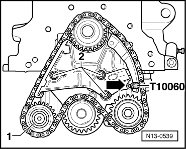
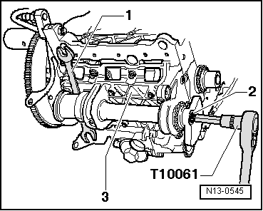
–  Lock balancing shaft with open-end wrench -1-.
  Note
The open-end wrench must be positioned in the centre for the safety weight of the balancing shaft and at right angles to the balancing shaft.
–  Loosen fixing bolt -2- for balancing weight.
  Note
Only loosen fixing bolt -2- for balancing weight, do not unscrew.
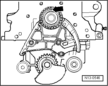
–  Unscrew retaining frame -3- from cylinder block and remove retaining frame with balancing shaft.
–  Lay aside retaining frame on a clean surface.
–  Unscrew fixing bolt from the balancing weight.
–  Remove balancing weight and chain sprocket from the balancing shaft.
–  Turn balancing shaft in such a way that it can be taken out of its bearing.
Install
–  Oil work surfaces of the bearing.
–  Insert balancing shaft in the bearing.
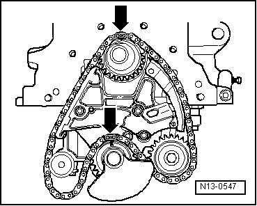
–  Slide chain sprocket and balancing weight onto the balancing shaft.
  Note
Assembly of chain sprocket and balancing weight is only possible in one position.
–  Tighten fixing bolt for balancing weight and chain sprocket by hand.
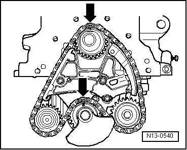
–  Screw retaining frame onto cylinder block clearance free and by hand.
  Note
t  When installing the retaining frame ensure, that the dowel sleeve is seated in the cylinder block and the O-ring in the retaining frame.
t  Align retaining frame in such a way, that it is aligned on the belt pulley side with the cylinder block outer side.
–  Screw retaining frame with balancing shaft onto cylinder block.
Tightening torque: 20 Nm.
–  Check if the retaining frame is aligned on the belt pulley side with the cylinder block outer side.
  N13-0545
–  Lock balancing shaft with open-end wrench -1- according to the illustration.
  Note
The open-end wrench must be positioned in the centre for the safety weight of the balancing shaft and at right angles to the balancing shaft.
–  Tighten fixing bolt -2- for balancing weight.
Tightening torque: 100 Nm + torque a further 90° (1/4 turn).
  Note
Fixing bolt is an antifatigue bolt and must always be replaced.
–  Install chain tensioner.
Tightening torque: 8 Nm + torque a further 90° (1/4 turn).
  Note
Fixing bolts for chain tensioner are antifatigue bolts and must always be replaced.
–  Clean chain with a non-fluffy cloth.
  N13-0545
–  Check, if the marking -arrow- at the chain sprocket of the crankshaft is located at the top.
  N13-0546
–  Fit chain onto chain sprocket of crankshaft, onto chain sprocket of oil pump and onto chain sprocket of balancing shaft. While doing so the markings of the colour marked chain links -arrows- at chain sprocket of crankshaft and at chain sprocket of balancing shaft must be opposite each other, as shown.
  Note
Colour marked chain links are additionally marked with a notch.
–  Insert chain sprocket for guide pulley into the chain and screw chain sprocket for guide pulley onto retaining frame.
Tightening torque: 20 Nm.
–  Remove locating pin -T10060A- from chain tensioner.
  N13-0547
–  Check if the markings of the colour marked chain links -arrows- at chain sprocket of crankshaft and at chain sprocket of balancing shaft are opposite each other.
  Note
Colour marked chain links are additionally marked with a notch.
–  Install the sealing flange on the belt pulley side → Chapter.
–  Install cover for balancing shaft.
Tightening torque: 5 Nm.
  Note
t  Oil O-ring for oil pump and inner shank of cover before installing the cover.
t  Pay attention to correct fitting of the sealing tape in the cover.
t  When installing the cover ensure that it locks into the retaining frame.
–  Installing the oil pan → Chapter.
–  Installing the timing belt → Chapter.
  N13-0540

Engine cooling > < Balancing shaft and retaining frame - Summary of components