skoda Workshop Repair Guides

Skoda Workshop Service and Repair Manuals

Removing and installing gasket rings and flywheel > < For engines with identification characters AWY, BMD
For engines with identification characters AZQ, BME
Removing the camshaft sprockets
–  Interlock camshafts and crankshaft at TDC for cylinder 1 → Chapter.
–  Remove timing case → Chapter.
–  Lock control chain tensioners → Chapter.
–  Remove control chain tensioners with rubber stop.
–  Remove the camshaft screws and take out the camshaft sprockets.
–  Screw in the crankshaft screw with housing and belt pulley - crankshaft.
   Tightening torque: 90 Nm + torque a further 45° (1/8 turn)
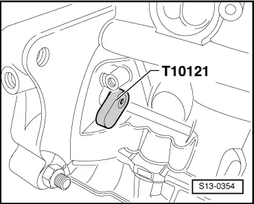
–  Remove the fixing bolt -T10121- and turn the crankshaft 45° against the direction of rotation of the engine.
Work can be performed on the valve drive while it is in this position.
Installing the camshaft sprockets, setting the timing
l  The pistons must not be positioned at top dead centre.
  Note
t  To turn the camshaft when the sprocket has been removed one can screw in a screw with two washers to a maximum of 50 Nm + 45° (1/8 turns) into the camshaft and turn the camshaft. The pistons must not be at TDC.
t  The central screws of the camshafts and the washers of the sprockets on engine with identification characters AZQ are to be replaced when the camshafts are removed.
t  
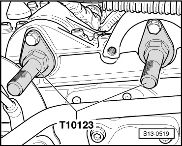
The camshaft fixer/locator -T10123- must not be used as a fixing lever to loosen and tighten up the camshaft screws.
t  The engine can be easily turned once the spark plugs have been removed.
   
–  Position camshafts to TDC of cylinder 1 and lock into place → Chapter.
–  Screw out the camshaft screws.
–  Remove oil residues on the camshaft studs and camshaft sprockets in the points of contact using a clean cloth.
–  Place the camshaft sprockets with the control chain laid on it on the camshafts and screw in the new camshaft screws so that the camshaft sprockets can still turn.
–  Install tensioner with rubber stop → Chapter.
–  Tension control chain → Chapter.
  S13-0519
–  Turn the crankshaft through a further 45° in the direction of rotation of the engine to TDC for cylinder 1 and interlock.
  Note
t  If the crankshaft is turned beyond TDC for cylinder 1 (observe the marking on the flywheel) then it should turned back and the TDC for cylinder 1 set again.
t  If the crankshaft is turned further it will collide with the piston on the valves.
  S13-0354
–  Tighten the screw -2- of the camshaft chain sprockets -1- to 50 Nm (use counterholder -MP1-216-).
–  Then, torque the bolts a further 90° (1/4 turn) with a rigid wrench.
   Tightening torque: 50 Nm + torque a further 90° (1/4 turn)
  Note
The assistance of a 2nd mechanic is required for this work.
–  Carefully crank engine at least 2 revolutions to ensure that no valve touches the piston when the engine is started, check timing again → Chapter.
Further installation occurs in reverse order.
–  Check position of camshaft to crankshaft in the display group 012 display field 3 and 4 → Vehicle diagnostic tester.
  S13-0370

Removing and installing gasket rings and flywheel > < For engines with identification characters AWY, BMD