skoda Workshop Repair Guides

Skoda Workshop Service and Repair Manuals

Testing intake manifold preheating > < Testing components
Inspecting the injection rate, tightness and jet formation of the injectors
Special tools and workshop equipment required
t  
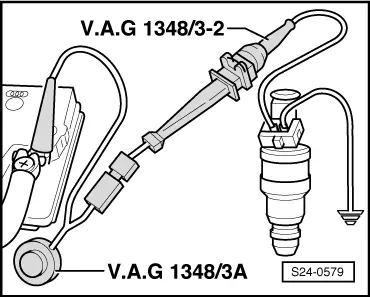
Remote control, e.g. -V.A.G 1348/3A-
t  Adapter, e.g. -V.A.G 1348/3-2-
t  
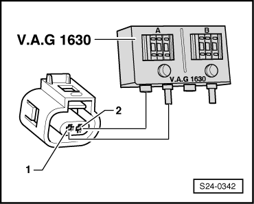
Digital potentiometer, e.g. -V.A.G 1630-
t  Measuring tool set, e.g. -V.A.G 1594 A, B, C-
t  Hand multimeter, e.g. -V.A.G 1602-
Test condition
l  Fuel pump relay O.K.
l  Fuel pump o.k.
l  Fuel temperature 15...20°C, fuel must be according to the valid standards.
Test sequence
–  If necessary remove engine cover with air filter → Chapter.
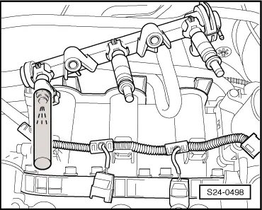
–  Remove fuel strip together with installed injectors → Chapter. The fuel hoses remain connected.
Testing jet formation and tightness
–  Disconnect plug at coolant temperature sender -G62- → Chapter.
   
–  Connect the digital potentiometer with auxiliary lines on both contacts of the plug connection and set to the connected side 15 kΩ.
  Note
Always check that it is only the checked valve which is connected up.
–  Disconnect the plug from the other injection valves.
  S24-0342
–  Hold a small vessel under the injection valve to be tested.
–  Operate the starter (a second person is needed here). The injection valve must emit a pulsed jet of fuel.
–  Repeat test at the other injectors.
–  Then check the injection valves for tightness. No more than 2 drops/min may trickle out.
If the fuel loss is greater than this:
–  Switch off ignition.
–  Replace the faulty injector → Chapter.
Testing fuel injection rate
  Note
When testing the injection rate also check the jet formation. The jet must be the same for all valves.
–  Insert injector to be tested in a measuring glass.
  S24-0498
–  Connect one contact of injector to battery mass.
–  Connect the second contact of the injector to the remote control.
–  Connect terminal to battery positive terminal.
  S24-0579
–  Connect battery positive terminal and fuse socket No. 61 with adapter cable and adapter -V.A.G 1348/3-2-.
The fuel pump must run.
–  Operate remote control for 30 seconds.
–  Repeat test at the other injectors. Always use a new measuring glass.
–  Once all the injectors have been driven, position the graduated measuring glasses on an even base.
–  Switch off voltage supply of fuel delivery unit.
–  Compare the individual quantities of fuel injected.
For engine with identification characters AWY, BMD
Specified value: 81 ... 88 ml per valve.
For engine with identification characters AZQ, BME
Specified value: 84 ... 91 ml per valve.
For all vehicles
If the measurement obtained for one or several injectors is not within the specification:
–  Replace the faulty injector → Chapter.
Installation of the injector occurs in reverse order. Pay attention to the following:
t  Replace the O-rings and all the injectors and moisten lightly with clean engine oil.
t  Insert injectors vertically and into the correct position in the fuel strip and secure with retaining clips.
t  Fit fuel strip with secured injectors onto the cylinder head and screw up at the same time → Chapter.
  S01-0094

Testing intake manifold preheating > < Testing components