skoda Workshop Repair Guides

Skoda Workshop Service and Repair Manuals

Repairing the hydraulic control unit > < Electric/electronic components and fitting locations ABS/EDL/TCS Mark 60
Removing and installing the hydraulic control unit and the bracket
  Note
Make absolutely sure that no brake fluid gets into the plug connector housing of the control unit. This may result in the corrosion of the contacts and to system failure. Carefully clean out the plug connector housing with compressed air if it gets dirty.
Special tools and workshop equipment required
t  Vehicle system tester -V.A.G 1552-
t  Diagnostic cable -V.A.G 1551/3, 3A, 3B oder 3C-
t  
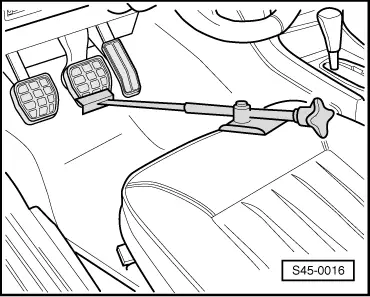
Brake pedal load, e.g. -V.A.G 1238/B-
t  Caps from the repair set SP no. -1 HO 698 311 A-
t  Brake filling and bleeding device, e.g. -VAS 5234-
t  Extraction bottle (commercially available)
t  Brake fluid → Chapter
   
1 - Hydraulic control unit
t  the hydraulic pump -V64-, the hydraulic unit -N55- and the ABS control unit -J104- form the hydraulic control unit.
t  the hydraulic control unit must be removed and installed completely → Chapter
t  the connections of the brake lines are embedded on the hydraulic control unit
t  repairing → Chapter
2 - Support
3 - Nut, 20 Nm
4 - 8 Nm
5 - Brake line, 14 Nm
t  Hydraulic unit to wheel cylinder/rear left brake caliper
6 - Brake line, 14 Nm
t  Hydraulic unit to wheel cylinder/rear right brake caliper
7 - Multi-pin connector/control unit
t  47-pin
t  Do not disconnect the plug connection before the self-diagnosis is complete. switch off the ignition before disconnecting the plug connector.
8 - Brake line, 14 Nm
t  between master brake cylinder/push rod piston circuit and hydraulic unit
9 - Brake line, 14 Nm
t  hydraulic unit to front left brake caliper
10 - Brake line, 14 Nm
t  between master brake cylinder/floating piston circuit and hydraulic unit
11 - Brake line, 14 Nm
t  Hydraulic unit to front right brake caliper

Remove the hydraulic control unit
  Note
t  Before disconnecting the battery determine the code of the radio sets fitted with anti-theft coding.
t  After connecting the battery, check the vehicle equipment:
–  on vehicles with radio encoding, carry out the coding,
–  set clock,
–  initialise power windows on vehicles fitted with power windows → BookletOctavia.
–  Disconnect battery.
  Note
The following 2 work steps do not apply to the 1.4 ltr./55 kW engine:
   
–  Disconnect the plug -1- of the air mass meter from the air guide pipe of the air filter.
–  Unscrew screws -2- at the air filter -3- and lay it aside.
–  Remove the relay carrier above the brake servo unit on diesel engines.
–  Using an extraction bottle extract as much brake fluid as possible from the brake fluid reservoir.
  A45-0041
–  Press brake pedal and lock in place with brake pedal load, e.g. -V.A.G 1238/B-.
–  Attach the bleeder hose of the bleeding bottle onto the bleeder screw of the front left brake caliper and open the bleeder screw.
–  Close the bleeder screw once the brake fluid flowed out.
–  Disconnect the bleeder hose from the bleeder screw.
  S45-0016
–  Release the multi-pin connector and remove it from the control unit -arrows-.
  Note
Make sure that no brake fluid gets onto the contacts.
–  In order to collect the brake fluid, position an absorption fleece under the hydraulic control unit.
  Note
Do not bend the brake lines around the hydraulic control unit.
  S45-0085
–  Screw out the brake lines from the master brake cylinder to the hydraulic unit, see -arrows-, and protect them against dirt with the caps from the repair set.
–  On vehicles with the steering located on the left, tie up the unscrewed brake lines with a welding wire as far to the top until the cable extremities protrude beyond the brake fluid gauge of the expansion reservoir -arrows-.
–  Unscrew the remaining brake lines from the hydraulic unit.
–  The connections of the hydraulic lines on the hydraulic unit must be closed with the screw plugs from the repair set.
  S45-0092
–  Unclip the cable for clutch control -arrow A-.
–  Unscrew the screws -arrows B- on the bracket for the hydraulic control unit.
–  Remove the hydraulic control unit .
Install the hydraulic control unit
  Note
Only then remove plugs from the hydraulic unit when the relevant brake line is installed.
–  Screw hydraulic control unit onto bracket.
  Note
Do not tighten screws. This facilitates the screwing of the individual brake lines onto the hydraulic control unit.
–  Connect the brake line to the hydraulic control unit and tighten → Chapter.
  S45-0093
–  Tighten the hydraulic control unit -arrows B-.
–  Clip on the cable for clutch control -arrow A-.
–  Insert the multi-plug connector on the control unit and lock.
Further installation occurs in reverse order.
–  Connect battery → Electrical System; Rep. gr.27.
–  Bleeding Brake System → Chapter.
–  Code the control unit → Chapter.
–  Interrogate the fault memory → Chapter.
–  Erasing fault memory → Chapter.
  S45-0093

Repairing the hydraulic control unit > < Electric/electronic components and fitting locations ABS/EDL/TCS Mark 60