skoda Workshop Repair Guides

Skoda Workshop Service and Repair Manuals

Replacing camshaft gasket rings > < Checking the axial play of the camshafts
Removing and installing camshafts and camshaft adjuster
(with cylinder head installed)
Special tools and workshop equipment required
t  Torque wrench
t  Counterholder -MP1-216 (3036)-
t  Holder for the chain tensioner -3366-
t  Rig pin -T40011-
t  Clamp bolt -T10092-
t  Sealant -D 454 300 A2-
Removing
–  Remove the V-ribbed belt and clamping fixture → Chapter.
–  Remove top toothed belt guard.
   
–  Rotate crankshaft at central bolt of crankshaft timing belt sprocket in direction of rotation of engine and position to TDC marking of cylinder 1 -arrows-.
–  Remove cylinder head cover → Chapter.
  A15-0024
–  Screw the clamping bolt -T10092- into the clamping fixture for the timing belt.
–  Tension pressure piston of tensioning device just sufficiently to enable the pressure piston to be secured with a locking pin (e.g. -T40011-).
–  Take toothed belt off camshaft sprocket.
–  Turn crankshaft at central bolt of crankshaft timing belt sprocket approx. 45° in the opposite direction of rotation of engine (before TDC marking for cylinder 1) in such a way that no piston is positioned at TDC.
–  Loosen bolts of camshaft sprocket (use counterholder - MP1-216 (3036)-).
–  Pull off camshaft sprocket.
–  Remove the camshaft housing and take out the oil deflector.
–  Remove the hall sender and the trim of the hall sender.
  N15-0407
–  Once again check the position of the camshafts for TCD cylinder 1:
   Both markings on the camshaft sprockets must be located opposite the arrows on the bearing caps -arrows-.
If the original chain is to be re-used:
  A15-0213
–  Clean the drive chain and the chain wheels of the camshafts opposite the two -arrows- on the bearing caps and mark the installed position using a colour marking.
t  The distance between the two -arrows- or colour markings is 16 rollers on the drive chain.
  Note
Do not mark the chain with a punch mark, notch or any other similar system!
Further procedure for all the chains:
  A15-0068
–  Secure the camshaft adjuster using the holder for the chain tensioner -3366-.
  Note
Excessively strong tightening of the holder for the chain tensioner -3366- can cause damage to the camshaft adjuster.
  S15-0092
–  First remove bearing caps -3- and -5- of the inlet and outlet camshaft.
–  Remove the double bearing cap.
–  Remove both bearing caps on the chain sprockets of the inlet and outlet camshaft.
–  Release the fixing screws of the camshaft adjuster.
–  Loosen and remove bearing caps -2- and -4- for the inlet and outlet camshaft alternately crosswise.
–  Remove the inlet and outlet camshaft with camshaft adjuster.
Install
l  The pistons must not be positioned at top dead centre.
l  The dowel sleeves of the bearing cap and the camshaft adjuster must be inserted in the cylinder head.
  A15-0047
–  Replace the rubber metal seal for the camshaft adjuster and coat the -shaded area- lightly with sealant -D 454 300 A2-.
If the original chain is to be re-used:
  A15-0027
–  Position the chain onto the camshaft chain sprockets according to the colour markings -arrows-.
The distance between the two colour markings on the chain must be 16 rollers.
When installing a new chain:
  A15-0212
–  Lay the chain on the camshaft chain sprockets as shown in the illustration.
The illustration shows where one must position the first 1st and 16th roller on the camshaft chain sprockets. Caution. - the marking -A- is slightly inserted opposite the tooth opening for fitting the 1st roller on the drive chain.
Further procedure for all the chains:
–  Insert the camshaft adjuster between the drive chain (a second mechanic is required).
–  Lay the camshafts with drive chain and camshaft adjuster in the cylinder head.
–  Oil contact surfaces of camshafts.
–  Tighten camshaft adjuster to 10 Nm (note the fitting bushes).
  Note
When installing the bearing cap ensure that the marking on the inlet side is legible.
  A15-0207
–  Screw in the bearing caps -2- and -4- for the inlet and outlet camshaft alternately crosswise, then tighten the screws to 10 Nm (note the fitting bushes).
–  Install both bearing caps on the chain sprockets of the inlet and outlet camshaft and tighten screws to 10 Nm (note the fitting bushes).
  A15-0047
–  Remove the holder for the chain tensioner -3366-.
  A15-0040
–  Check correct position of the camshafts:
   Both markings on the camshaft sprockets must be located opposite the arrows on the bearing caps -arrows-.
  Note
If necessary turn the camshafts in both directions in order to achieve the correct position of the markings
  A15-0213
–  Lightly coat the shaded surface of the double bearings cap with sealant -D 454 300 A2-, install and tighten the screws to 10 Nm (note the fitting bushes).
–  Install the other bearing caps and tighten the screws to 10 Nm (note the fitting bushes).
–  Replace the gasket rings for the inlet and outlet camshaft → Chapter.
  A15-0028
–  Install camshaft timing gear.
t  check fitting position:
   The small stay on the camshaft sprocket points outwards -arrows- and the TDC marking on the cylinder 1 is visible from the front.
–  Tighten fixing screw for camshaft sprocket to 65 Nm (use counterholder -MP1-216 (3036)-).
–  Place the trim for the hall sender with the peg in the notch of the inlet camshaft.
–  Install the disc (with the cone pointing outwards) and tighten to 25 Nm.
–  Install hall sender and tighten to 10 Nm.
–  Install cylinder head cover → Chapter.
  Note
When turning the camshafts the valves may touch the piston in TDC. Therefore the pistons must not be at TDC. Risk of damaging valves and pistons.
  S15-0116
–  Bring the marking on the camshaft sprocket in line with the marking on the cylinder head cover.
–  Turn the crankshaft at the central bolt of the crankshaft timing belt sprocket to approx 45° in direction of engine and bring the marking on the vibration damper in line with the marking on the bottom timing belt guard.
  A15-0024
–  Check whether the TDC marking for cylinder 1 on the flywheel and the reference mark are aligned -arrow-.
–  Place the timing belt onto the camshaft sprocket.
  A13-0045
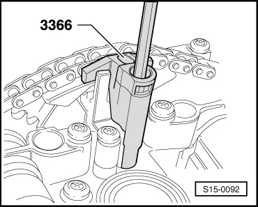
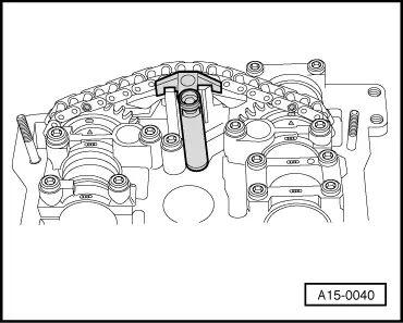
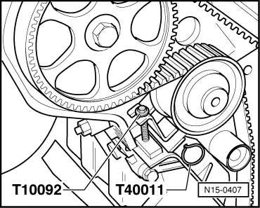
–  Pull out rig pin -T40011 - and slacken pressure piston of tensioning device. Screw out the tensioning screw -T10092-.
–  Install top toothed belt guard.
–  Install the V-ribbed belt and clamping fixture → Chapter.
  Note
t  After installing the camshafts, the engine must not be started for about 30 minutes. The hydraulic clearance compensation elements must settle (otherwise valves would strike the pistons).
t  After carrying out work on the valve gear, carefully crank engine in the direction of running at least 2 revolutions to ensure that no valve touches the piston when the engine is started.
  N15-0407

Replacing camshaft gasket rings > < Checking the axial play of the camshafts