
Octavia Mk1
| Parts of cooling system engine side |
| connection diagram for coolant hoses → Chapter |
| Engine with identification characters ATD |

| 1 - | 15 Nm |
| 2 - | Coolant pump |
| q | check smooth operation |
| q | Check fitting position |
| q | removing and installing → Chapter |
| 3 - | O-ring |
| q | replace |
| 4 - | to expansion reservoir |
| q | to top |
| 5 - | Top coolant pipe |
| q | screwed onto the cylinder head cover |
| 6 - | Connection fittings |
| q | for heat exchanger |
| 7 - | Distributor part |
| 8 - | Sender for the coolant temperature -G62 - |
| q | inspect → 1.9 l/74 kW (TDI) Engine, Fuel Injection and Glow Plug System; Rep. Gr.28 |
| 9 - | Retaining clip |
| q | check for firm seating |
| 10 - | Gasket ring |
| q | check for firm seating |
| q | replace |
| 11 - | Connection fittings |
| q | for cylinder head |
| 12 - | 10 Nm |
| 13 - | Distributor part |
| 14 - | 40 Nm |
| 15 - | to ATF radiator |
| q | to top |
| 16 - | Coolant pipe |
| 17 - | to expansion reservoir |
| q | to bottom |
| 18 - | to ATF radiator |
| q | to bottom |
| 19 - | Connection fittings |
| q | to coolant thermostat |
| 20 - | Coolant regulator |
| q | removing and installing → Chapter |
| 21 - | Oil cooler |
| q | removing and installing → Chapter |
| Engine with engine code AXR |
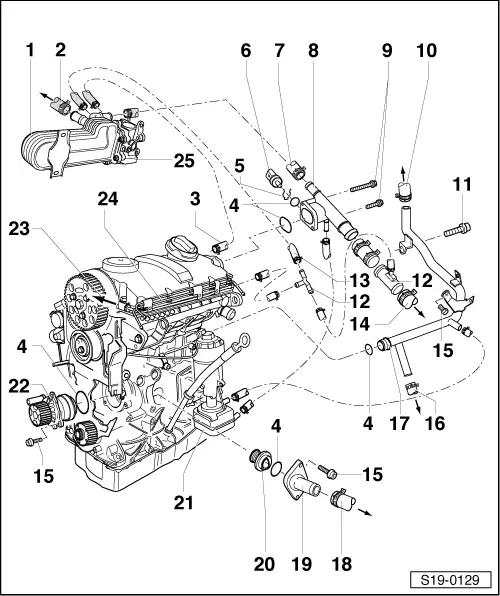
| 1 - | Radiator for exhaust gas recirculation |
| q | removing and installing → Chapter |
| 2 - | to heat exchanger |
| q | Feed line |
| 3 - | to changeover valve of radiator for exhaust gas recirculation |
| 4 - | O-ring |
| q | replace |
| 5 - | Retaining clip |
| q | check tightness |
| 6 - | Sender for coolant temperature -G62- |
| 7 - | to radiator for exhaust gas recirculation |
| 8 - | Connection fittings |
| q | for cylinder head |
| 9 - | 10 Nm |
| 10 - | to heat exchanger |
| q | Return-flow line |
| 11 - | 40 Nm |
| 12 - | Distributor part |
| 13 - | from changeover valve of radiator for exhaust gas recirculation |
| 14 - | to ATF radiator |
| q | to top |
| 15 - | 15 Nm |
| 16 - | to expansion reservoir |
| q | to bottom |
| 17 - | Coolant pipe |
| 18 - | to ATF radiator |
| q | to bottom |
| 19 - | Connection fittings |
| q | to coolant thermostat |
| 20 - | Coolant regulator |
| q | removing and installing → Chapter |
| q | test: heat up regulator in a water bath |
| q | Start of opening approx. 87°C |
| q | Full opening approx. 102°C |
| q | Stroke min. 8 mm |
| 21 - | Oil cooler |
| q | removing and installing → Chapter |
| 22 - | Coolant pump |
| q | check smooth operation |
| q | Check fitting position |
| q | removing and installing → Chapter |
| 23 - | to expansion reservoir |
| q | to top |
| 24 - | Top coolant pipe |
| q | screwed onto the cylinder head cover |
| 25 - | Radiator flap for exhaust gas recirculation |
| q | removing and installing → Chapter |