
Octavia Mk1
 Note
Note| t | The clutch must only be disassembled for cleaning and for carrying out a visual inspection. |
| t | On certain gearboxes, the clutches -K1- and -K3- can be pressed together. |
| t | press off -K1- from -K3- → Chapter. |
| t | press -K1- onto -K3- → Chapter. |

| 1 - | Circlip |
| q | Differing thickness |
| q | mark after removing and install again in same position |
| q | do not interchange with circlips of other clutches |
| 2 - | Pressure plate |
| q | Fitting position: smooth side points to the plates |
| q | install the offset side to the circlip Pos. 1 |
| 3 - | Inner plate |
| q | Piece number → Chapter |
| q | place new inner plate into ATF for 15 minutes before installing |
| 4 - | Outer plate |
| q | Piece number → Chapter |
| 5 - | Pressure plate |
| q | caulked with wave spring washer Pos. 6 |
| q | insert with caulked wave spring washer pointing towards the piston |
| 6 - | Wave spring washer |
| q | caulked with pressure plate Pos. 5 |
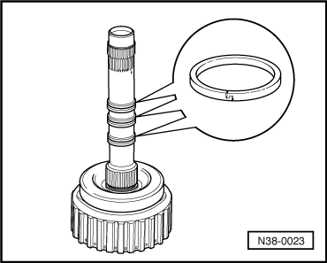
| 7 - | Circlip |
| q | Differing thickness |
| q | removing and installing → Fig. |
| q | do not interchange with circlips of other clutches |
| q | mark after removing and install again in same position |
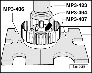
| 8 - | Piston cap |
| q | under high spring tension |
| q | The sealing lips are vulcanized to the piston cap |
| q | removing and installing → Fig. |
| q | moisten sealing lips with ATF before inserting |
| q | turn piston cap slightly when installing |
| 9 - | Spring |
| q | insert between piston and piston cap |
| 10 - | Piston |
| q | The sealing lips are vulcanized to the pistons |
| q | moisten sealing lips with ATF before inserting |
| q | turn piston slightly when installing |
| 11 - | Clutch bell with turbine shaft |
| q | there are two different versions of turbine shafts → Chapter |
| q | differs in height depending on the number of outer and inner plates |
| q | The gearbox identification characters are assigned to the version |
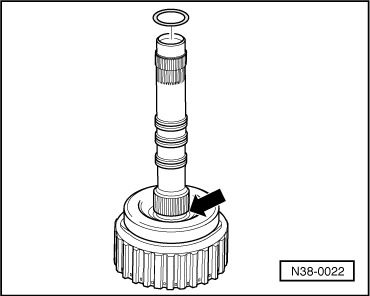
| 12 - | O-ring |
| q | always replace → Electronic Catalogue of Original Parts |
| q | installing → Fig. |
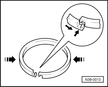
| 13 - | Piston ring |
| q | removing and installing → Fig. |
| q | check for correct position → Fig. |
|
|
|
|
|
|
|
|