skoda Workshop Repair Guides

Skoda Workshop Service and Repair Manuals

Removing and installing drive shaft with inner tripod joint AAR3300i > < Removing and installing a drive shaft with CV joint
Removing and installing drive shaft with inner tripod joint AAR2600i
Removing:
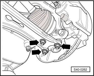
–  Unscrew screw for securing the drive shaft to the wheel hub:
t  Hexagon screw → Chapter
t  Twelve-sided bolt → Chapter
  Note
t  At the same time the vehicle must not be standing on its wheels, otherwise the wheel bearing will be damaged.
t  If the screw is loose, the wheel bearings must not be loaded.
t  If the wheel bearings are loaded through the vehicle's own weight, the wheel bearing will be initially damaged. This shortens the life of the wheel bearing.
t  
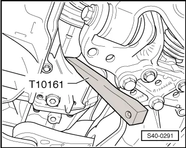
When moving vehicles with drive shaft removed, it is advisable to install an external joint instead of the drive shaft and tighten with a torque of 120 Nm.
–  Remove wheel.
–  Remove noise insulation → Body Work → Rep. gr.50.
–  Remove drive shaft screening from the engine (if present).
   
–  Unscrew the nuts -arrows-.
–  Pull the wheel-bearing housing with steering joint out of the track control arm.
–  Pull the drive shaft out of the wheel hub and attach to the body.
  S40-0262
–  Insert the wedge -T10161- between the gearbox housing and the tripod joint.
–  Press inner joint with a knock from a hammer onto the wedge -T10161- out of the gearbox.
–  Remove the drive shaft.
Installing:
–  Insert new circlip in the groove of the drive shaft.
–  Engage outer and internal serration of joint part and gearbox.
–  Grasp the drive shaft with the hand and slide it up to the stop in the joint part.
–  Now slide the joint part with the drive shaft in the gearbox.
  Note
t  Avoid jolting load.
t  Under no circumstances use a hammer or similar striking tools!
–  Check safe seating of the drive shaft in the gearbox by pulling the drive shaft against the resistance of the circlip.
  Note
For this inspection pull only on the joint part and not on the drive shaft.
–  Insert outer joint as far as possible into the serration of the wheel hub.
–  Attach drive shaft screening to the engine (if present).
–  Install the noise insulation → Body Work → Rep. gr.50.
  S40-0291
–  Screw steering joint to the track control arm -arrows-.
  Note
Make sure the boot is neither damaged nor twisted.
–  Tighten screw for securing the drive shaft to the wheel hub:
t  Hexagon screw → Chapter
t  Twelve-sided bolt → Chapter
  Note
At the same time the vehicle must not be standing on its wheels, otherwise the wheel bearing will be damaged.
–  Tighten wheel.
  S40-0262
Tightening torques:
Drive shaft to wheel hub with wheel bearing „hexagon screw“
t  Use new screw
t  Vehicle must not be standing on its wheels for tightening the screw
200 Nm + 180°
Drive shaft to wheel hub with wheel bearing „twelve-sided bolt“
t  Use new screw
t  Vehicle must not be standing on its wheels for tightening the screw
70 Nm + 90°
Steering joint to track control arm 
t  Track control arm made of steel casting
60 Nm
t  Track control arm made of steel sheet
100 Nm
Drive shaft screening25 Nm
Wheel bolts120 Nm


Removing and installing drive shaft with inner tripod joint AAR3300i > < Removing and installing a drive shaft with CV joint