skoda Workshop Repair Guides

Skoda Workshop Service and Repair Manuals

Removing and installing top suspension arm > < Remove and install rear left vehicle level sensorG76 in the vehicle
Removing and installing rear suspension
Special tools and workshop equipment required
t  Engine/gearbox jack, e.g. -V.A.G 1383/A-
t  Tensioning strap -T10038-
t  Fixing device -T10096-
Removing assembly carrier with its component parts:
  Note
The removal of the rear axle parts is carried out in the same way on both sides.
–  Remove wheels.
–  Remove coil springs → Chapter.
   
–  Disconnect the plug -1- on vehicles fitted with automatic headlight range control.
–  Take the speed sensor out of the wheel bearing housing.
  S42-0219
–  Release screw -arrow-.
  S42-0178
For the version with the spring clip
–  Slacken the spring clip -1- for the hand-brake cable.
–  Press the lever -2- in the -direction of the arrow- and while doing so unhook the hand-brake cable -3-.
  S42-0203
For the version with the spring bushing
–  Press the lever -2- in the -direction of the arrow- and while doing so unhook the hand-brake cable -3-.
–  Slacken the spring bushing -1- for the hand-brake cable from the bracket on the brake caliper.
Continued for all versions
–  Unscrew screw for hand brake cable holder from trailing arm.
  S42-0302
–  Unclip speed sensor cable from bracket -1--arrows-.
  S42-0238
–  Pull out the bracket for wiring -1- on both vehicle sides.
  S42-0298
–  Remove brake calipers: Unscrew the fixing screws from the brake carrier while counterholding the guide bolt.
–  Remove the brake caliper and e.g. secure with wire in such a way that the weight of the brake caliper does not burden or damage the brake hose.
  S46-0141
–  Mark the installed position of the bracket on the body.
–  Release screws -arrows-.
–  Unhook the rear silencer from the retaining strap on the assembly carrier → Engine → Rep. gr.26.
  S42-0182
–  Now lash the vehicle securely to the lift platform using tensioning straps -T10038-.
  WARNING
If the vehicle is not lashed, there is a risk of the vehicle toppling off the lift platform.
  S42-0211
–  Position engine/gearbox jack e. g. -V.A.G 1383/A- with universal gearbox mount -V.A.G 1359/2- under the assembly carrier and secure it with tensioning strap.
  S42-0212
–  Release screw -1- or -2- on both sides.
  Note
To provide a clearer illustration, only the left vehicle side is illustrated.
  A42-10026
–  Fix the position of the assembly carrier using two fixing devices -T10096-; tighten to 20°Nm.
  Note
The fixing devices -T10096- must only be tightened to maximum 20 Nm as otherwise the fixing bolt thread becomes damaged.
–  Unscrew the remaining two screws from the assembly carrier.
–  Carefully lower assembly carrier to maximum 30 mm.
  Note
Ensure adequate clearance of brake and electric lines when lowering.
  S42-0299
–  Unclip brake line -1--arrows-.
  Note
The fig. shows the assembly carrier from above and in the removed condition for purposes of clear presentation.
–  Lowering assembly carrier with attached parts.
Installing assembly carrier with its component parts:
Installation occurs in reverse order to removal. Pay attention to the following:
–  Perform chassis alignment → Chapter.
  S42-0300
Tightening torques:
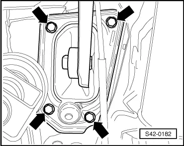
Mounting bracket on the body
t  Use new screws!
50 Nm +45°
Assembly carrier to body
t  Use new screws!
90 Nm + 90°
Shock absorber to wheel-bearing housing
t  Tighten in unladen weight position! → Chapter
180 Nm
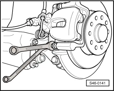
Brake caliper to brake carrier
t  Use new self-locking screws!
35 Nm
Wheel speed sensor8 Nm
Wheel bolts120 Nm


Removing and installing top suspension arm > < Remove and install rear left vehicle level sensorG76 in the vehicle