
Superb
| Disassembling and assembling pistons and conrods |

| 1 - | 30 Nm + torque a further 1/4 turn (90°) |
| q | replace |
| q | Oil thread and contact surface |
| 2 - | Conrod bearing cap |
| q | do not interchange |
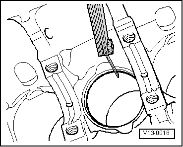
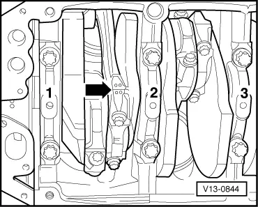
| q | mark assignment to cylinder -B- → Fig. |
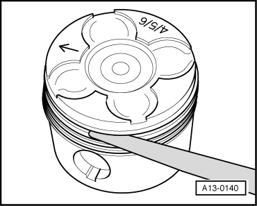
| q | Fitting location: take note of the markings on the casting -A- → Fig. |
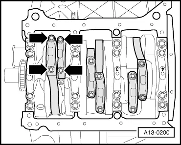
| 3 - | Bearing shell |
| q | Check fitting position |
| q | do not mix up used bearing shells (mark) |
| q | new axial play for each new conrod pair: 0.20...0.44 mm, wear limit: 0.60 mm |
| 4 - | Conrod |
| q | with a split bearing cap |
| q | always replace as a set only |
| q | mark assignment to cylinder -B- |
| q | Fitting location: take note of the markings on the casting -A- → Fig. |
| 5 - | Circlip |
| 6 - | Piston pin |
| q | if stiff, heat piston to 60° |
| q | with drift VW 222A removing and installing |
| 7 - | Piston |
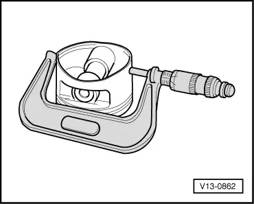
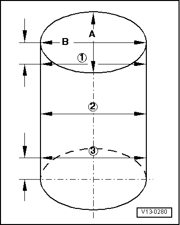
| q | Ø Piston: 78.253...78.261 |
| q | Ø Cylinder: 78.306...78.310 |
| q | with combustion chamber |
| q | mark installation position and matching cylinder |
| q | check → Fig. |
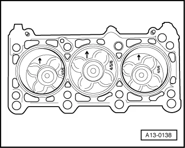
| q | Installation position and assignment of piston/cylinder → Fig. |
| q | arrow on piston crown faces towards the middle of the engine |
| q | use piston ring tensioning strap for installing |
| q | replace piston if there is any sign of crack formation on the piston body |
| q | inspect piston projection at TDC → Chapter |
| 8 - | Piston rings |
| q | Offset joint 120 ° |
| q | use piston ring pliers for removing and installing |
| q | marking “TOP” must face towards piston crown |
| q | Inspect gap clearance → Fig. |
| q | Inspect end clearance → Fig. |
| 9 - | 9 Nm |
| 10 - | Oil injection nozzle |
| q | for cooling pistons |
| Piston ring dimension in mm | New | Wear limit |
| 1. Compression ring | 0,20 ... 0,40 | 0,8 |
| 2. Compression ring | 0,80 ... 1,00 | 1,4 |
| Oil scraper ring | 0,25 ... 0,50 | 0,8 |
|
|
| Piston ring dimension in mm | New | Wear limit |
| 1. Compression ring | 0,100...0,135 | 0,150 |
| 2. Compression ring | 0,045...0,085 | 0,110 |
| Oil scraper ring | 0,025...0,065 | 0,090 |
|
|
|
|
 Note
Note
|
|
Note
|
|
Note
|
|