|
Timing, Check
 Remove Remove
Remove air cleaner housing with air intake hose and hot film
mass air flow meter – see illustration "Air Ducts".
Remove upper part of toothed belt cover – see operation
"Toothed Belt Cover – Upper Part, Remove and Install".
For version with AC: Remove ribbed V-belts – see operation
"Ribbed V-belts, Remove and Install".
Remove V-belt – see operation "V-belt, Remove and
Install".
Remove lower part of toothed belt cover – see operation
"Toothed Belt Cover – Lower Part, Remove and Install".
Check toothed belt tension, adjust if necessary – see
operation "Toothed Belt Tension, Check".
|
Remove engine vent hose from camshaft housing cover.
Remove camshaft housing cover from camshaft housing.
 Adjust Adjust
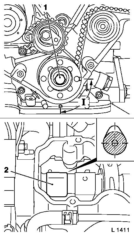
At fastening bolt (1) of toothed belt drive gear, turn
crankshaft in engine rotational direction to approx. 90°
(dimension I) before "1st cylinder TDC".
 Inspect
1st cylinder exhaust cam (2) must point vertically upwards.
|
|
 Install
|
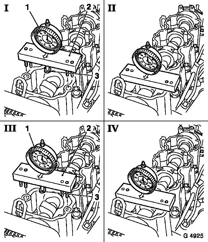
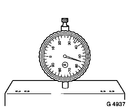
Insert Dial gauge MKM-571-B (1) in Tool KM-661-1 (2) –
arrow on KM-661-1 points towards engine timing side. Attach base
(3) Ø 10 mm to dial gauge. To adjust dial gauge, left
positioning pins of tool (I+II) must be seated in bores of camshaft
housing. Set probe of dial gauge onto basic circle of 2nd cam
(intake, 1st cylinder). Set dial gauge to "0" – ensure that
the probe is not seated on the cam oil bore.
Caution
The Dial Gauge MKM-571 may be pre-tensioned by max. 0.5 mm,
otherwise the resulting measurement will be incorrect.
Offset Tool KM-661-1 with dial gauge to the left. Right
positioning pins (III+IV) must be seated in the bores of the
camshaft housing.
|
|
|
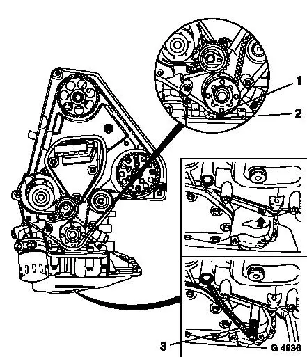
At fastening bolt of toothed belt drive gear, turn crankshaft in
engine rotational direction to just before "1st cylinder ignition
TDC". Insert TDC Centring Pin KM-951 (3) into opening on
transmission (arrow), at the same time at fastening bolt of toothed
belt drive gear, further turn crankshaft in engine rotational
direction until TDC centring pin engages in cylinder block or
crankshaft webs to the stop.
Inspect
In this position, mark (1) on toothed belt drive gear must align
with mark (2) on oil pump.
Note: Attach to
flywheel side with the engine removed or unflanged Transmission
KM-540-A.
|
|
Install
|
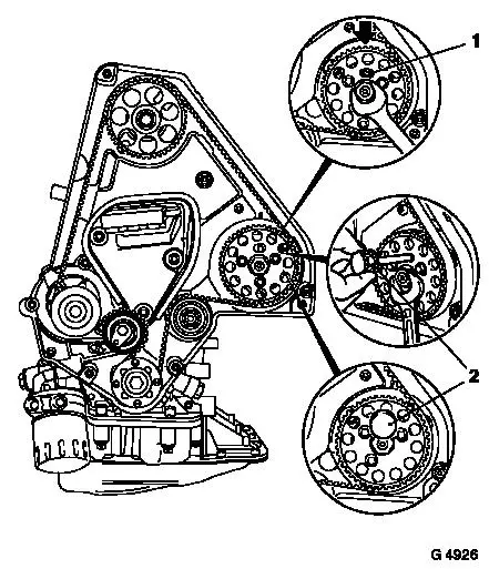
Mark out injection pump with Marker Pin KM-6011 (2).
Caution
With open-ended spanner turn injection pump flange until recess
(1) on injection pump pulley aligns with injection pump flange
recess and injection pump retaining bore (arrow).
Note: If the marker
pin could not be inserted then a basic adjustment must be performed
– see operation "Timing, Adjust".
|
|
 Measure
|
Read off value on Dial Gauge MKM-571-B.
Camshaft elevation nominal value: 0.55 mm ± 0.03 mm.
Note: If the measured
result does not agree with the nominal value, adjust timing –
see operation "Timing, Adjust".
Remove
Remove all retaining and adjusting tools.
|
|
Install
Install camshaft housing cover with new gasket to camshaft
housing – tightening torque – 8 Nm / 6 lbf. ft.
Attach engine bleeding hose to camshaft housing cover.
Install lower part of toothed belt cover – see operation
"Toothed Belt Cover – Lower Part, Remove and Install".
Install V-belt – see operation "V-belt, Remove and
Install".
For version with AC: Install ribbed V-belt – see operation
"Ribbed V-belt, Remove and Install".
Install upper part of toothed belt cover – see operation
"Toothed Belt Cover – Upper Part, Remove and Install".
Install air cleaner housing with air intake hose and hot film
mass air flow meter – see illustration "Air Ducts".
|
