|
Camshafts, Remove and Install
 Remove Remove
Remove air cleaner housing – see illustration "Air Ducts X
14 XE, Z 14 XE, X 16 XEL,Z 16 XE, Z 16 YNG" or "Air Ducts X 18 XE1,
Z 18 XE, Z 18 XEL".
Remove upper part of toothed belt cover – see operation
"Toothed Belt Cover – Upper Part, Remove and Install".
Remove ribbed V-belts – see operation "Ribbed V-belts,
Remove and Install".
Remove ribbed V-belt tensioner – see operation "Ribbed
V-belt Tensioner, Remove and Install".
Remove lower part of toothed belt cover – see operation
"Toothed Belt Cover – Lower Part, Remove and Install".
 Install
Screw fastening bolt for toothed belt drive gear in
crankshaft.
|
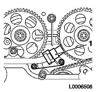
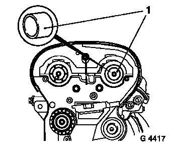
Remove
Detach camshaft sensor (1) from cylinder head and place to one
side.
|
|
|
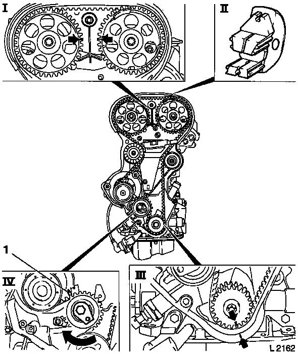
 Adjust Adjust
Turn crankshaft in the direction of engine rotation to "1st
cylinder TDC" (III). Marks on the camshaft pulleys must be aligned
(I).
Install
Fix camshaft pulleys in position with KM-852 (II).
Remove
Release fastening bolt for toothed belt tension roller (IV) and
turn adjusting eccentric in direction of arrow (clockwise) until
pointer (1) is located just before left stop.
Remove toothed belt and place to one side.
|
|
Remove ignition module – see operation "Ignition Module,
Remove and Install (X 14 XE, Z 14 XE, X 16 XEL, Z 16 XE, Z 16 YNG)"
or "Ignition Module, Remove and Install (X 18 XE1, Z 18 XE, Z 18
XEL)".
Remove cylinder head cover – see operation "Cylinder Head
Cover, Remove and Install".
Remove relevant camshaft pulley – see operation "Camshaft
Pulleys, Remove and Install".
|
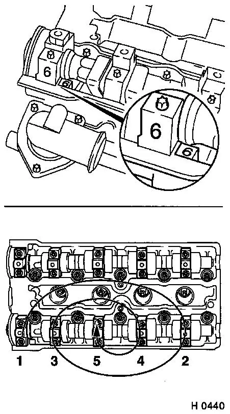
Caution
Note marking before dismantling camshaft bearing cover!
The camshaft must release evenly from the bearing seats.
Remove
Detach camshaft bearing caps working in inward spiral from
outside in steps of 1/2 up to 1 turn.
Detach camshaft bearing caps from cylinder head and remove
camshaft.
 Clean Clean
Clean sealing surfaces and remove gasket residues.
 Inspect
Check camshaft and bearing seats for wear, replace if
necessary.
|
|
Install
|
Coat sliding surfaces of hydraulic valve lifters and camshaft
with MoS 2 lubricating paste (grey). Insert
camshaft into cylinder head.
|
|
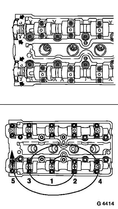
Caution
Code numbers on camshaft bearing caps must match those on
cylinder head.
Apply surface sealant (green) to sealing surface of guide
bearing (arrow).
Install
Install camshaft bearing cover at cylinder head and tighten in
spiral pattern from inside outwards – tightening torque 8 Nm
/ 6 lbf. ft.
|
Lightly coat sealing lip of the new seal ring with silicon
grease (white). Press seal ring into camshaft bearing cap using
KM-422 (1) – for this purpose use bolt and washer of camshaft
pulley.
Install camshaft sprockets – see operation "Camshaft
Sprockets, Remove and Install".
Install cylinder head cover – see operation "Cylinder Head
Cover, Remove and Install".
Install ignition module – see operation "Ignition Module,
Remove and Install (X 14 XE, Z 14 XE, X 16 XEL, Z 16 XE, Z 16 YNG)"
or "Ignition Module, Remove and Install (X 18 XE1, Z 18 XE, Z 18
XEL)".
|
|
|
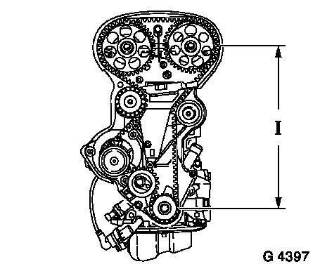
Install toothed belt – ensure that tensioned side (I) is
taut.
Caution
Note timing mark.
Adjust toothed belt tension – see operation "Toothed Belt
Tension, Adjust".
Attach camshaft sensor to cylinder head – insert bolts
with screw locking compound (red) – tightening torque 8 Nm /
6 lbf. ft.
Install lower part of toothed belt cover – see operation
"Toothed Belt Cover – Lower Part, Remove and Install".
Install ribbed V-belt tensioner – see operation "Ribbed
V-belt Tensioner, Remove and Install".
Install ribbed V-belt – see operation "Ribbed V-belt,
Remove and Install".
Install upper part of toothed belt cover – see operation
"Toothed Belt Cover – Upper Part, Remove and Install".
Install air cleaner housing – see illustration "Air Ducts
X 14 XE, Z 14 XE, X 16 XEL, Z 16 XE, Z 16 YNG" or "Air Ducts X 18
XE1, Z 18 XE, Z 18 XEL".
|
|
|
