|
Intake Manifold, Remove and Install (X 20 XEV, X
20 XER)
 Remove Remove
Disconnect ground cable from battery.
Remove air cleaner housing – see illustration "Air Duct (X
20 XEV, X 20 XER)".
Remove lower engine splash guard.
Remove ribbed V-belt – see operation "Ribbed V-belt,
Remove and Install (without Air Conditioning)" or "Ribbed V-belt,
Remove and Install (with Air Conditioning)".
|
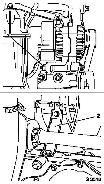
Release lower alternator fastening bolt (1).
Detach intake manifold support (2) from intake manifold and
release from cylinder block – swing support to one side.
|
|
Disconnect wiring harness plug from switchover valve solenoid
valve and throttle valve potentiometer. Unclip knock sensor wiring
harness plug from bracket and lay free.
|
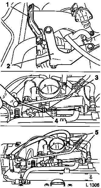
Remove alternator support (1) from intake manifold and
alternator. Remove alternator shackle (2) from alternator, intake
manifold and coolant flange – swing alternator to rear.
Lift retainer for accelerator Bowden cable (4) with screwdriver
and remove ball socket for accelerator Bowden cable (3) from ball
head.
For version with electronic cruise control: remove shackle for
cruise control Bowden cable from ball head – see operation
"Cruise Control – Bowden Cable, Remove and Install".
Detach engine vent hoses from cylinder head cover. Detach hose
for tank vent valve from throttle body.
Detach brake servo vacuum line and exhaust gas recirculation
valve vacuum hose from intake manifold.
Detach coolant hoses (5) from throttle body – collect
escaping coolant.
|
|
Reduce fuel pressure with Pressure Tester KM-J-34730-91 via
testing port – collect escaping fuel in suitable container
– observe safety regulations and national legislation.
|
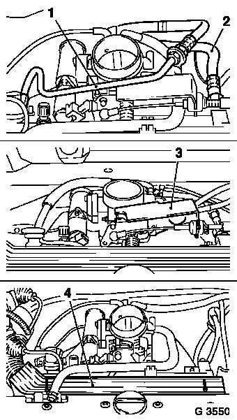
Detach fuel return line (1) from fuel pressure regulator and
detach Bowden cable bracket. Detach fuel feed line (2) from fuel
distributor pipe and lay aside to rear.
Detach Bowden cable retainers (3) from throttle body and lay
aside with Bowden cables towards rear.
Detach wiring harness plug from tank vent valve and idle air
control.
Detach ignition cable cover and disconnect wiring harness plug
from camshaft sensor.
Clip off crankshaft pulse pick-up cable and dynamic oil level
control from cylinder head cover and lay free.
Detach plug strip (4) from injectors and place to one side.
|
|
Detach rear left engine transport shackle.
For version with right hand drive and manual transmission:
Remove throttle body from intake manifold – see operation
"Throttle Body, Remove and Install".
|
Pull clip (1) out of connections on clutch master cylinder and
remove delivery line from connector – then bend clip slightly
together and re-insert in clutch master cylinder. Collect escaping
fluid.
Detach intake manifold from cylinder head and remove.
 Clean Clean
Clean sealing surfaces and remove gasket residues.
 Install
When replacing, transfer attaching parts.
|
|
Attach intake manifold to cylinder head with new gasket and new
fastening nuts – tightening torque 22 Nm / 16 lbf. ft.
For version with right-hand drive and manual transmission: push
delivery line into clutch master cylinder – must audibly
engage. Attach throttle body to intake manifold – see
operation "Throttle Body, Remove and Install".
Attach engine transport shackle to cylinder head –
tightening torque 20 Nm / 15 lbf. ft.
Connect plug strip to injectors – plug strip must engage
audibly – ensure correct seating.
Clip on crankshaft pulse pick-up cable and dynamic oil level
control to cylinder head cover.
Connect wiring harness plug to camshaft sensor.
Attach ignition cable cover to cylinder head cover –
tightening torque 3 Nm / 2.2 lbf. ft.
Connect wiring harness plug to tank vent valve, idle air
control, switchover valve solenoid valve and throttle valve
potentiometer.
Attach Bowden cable bracket to throttle body.
For version with electronic cruise control: attach shackle for
cruise control Bowden cable to ball head – see operation
"Cruise Control – Bowden Cable, Remove and Install".
Connect ball socket for accelerator Bowden cable to ball head
– ensure that retainer engages.
Attach fuel return line to fuel pressure regulator –
tightening torque 15 Nm / 11 lbf. ft.
Attach fuel return line to bracket for Bowden cables –
tightening torque 9 Nm / 6.5 lbf. ft.
Attach fuel feed lines to fuel distributor pipe –
tightening torque 15 Nm / 11 lbf. ft.
Attach coolant hose to throttle body and intake manifold.
Connect brake servo vacuum line and exhaust gas recirculation
valve vacuum hose to intake manifold.
Attach tank vent valve hose to throttle valve body.
Attach engine vent hose to cylinder head cover.
Attach alternator shackle to alternator, intake manifold and
coolant flange – tightening torque 20 Nm / 15 lbf. ft.
Attach alternator support to alternator and intake manifold
– tightening torque 20 Nm / 15 lbf. ft.
Clip knock sensor cable to bracket – note cable
routing.
Attach intake manifold support to intake manifold and cylinder
block – tightening torque 25 Nm / 18 lbf. ft.
Secure alternator to alternator support bracket (lower
alternator fastening bolt) – tightening torque 35 Nm / 26
lbf. ft.
Install ribbed V-belt – see operation "Ribbed V-belt,
Remove and Install (without Air Conditioning)" or "Ribbed V-belt,
Remove and Install (with Air Conditioning)".
Install lower engine splash guard.
Install air cleaner housing – see illustration "Air Duct
(X 20 XEV, X 20 XER)".
Connect ground cable to battery.
 Inspect
Charge and bleed cooling system – see operation "Cooling
System, Charge and Bleed" and "Cooling System, Check for
Leaks".
For version with manual transmission: Bleed hydraulic clutch
actuation – see operation "Hydraulic Clutch Actuation, Bleed
(F13/F17/F18/F23)" in group "K".
|
