|
Cylinder Head, Remove and Install
Caution
Remove cylinder head only with cold engine (room
temperature).
 Remove Remove
|
Detach battery ground cable.
Open coolant drain bolt – collect escaping coolant.
Remove air cleaner housing with air intake cover – see
illustration "Air Ducts (X 16 SZR)" and illustration "Air Ducts (Z
16 SE)".
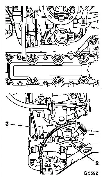
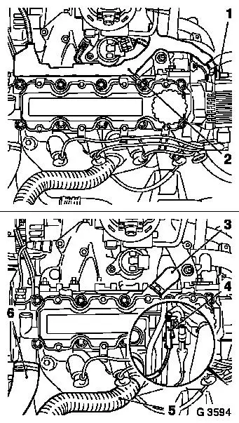
Remove engine bleeding hose (1) from camshaft housing cover.
Remove upper part of toothed belt cover – see operation
"Toothed Belt Cover – Upper Part, Remove and Install".
Remove ribbed V-belts – see operation "Ribbed V-belts,
Remove and Install".
Detach alternator support (3) from alternator and intake
manifold. Release alternator from alternator shackle (2) and swing
alternator rearwards.
|
|
|
Remove ribbed V-belt tensioner – see operation "Ribbed
V-belt Tensioner, Remove and Install".
Remove lower part of toothed belt cover – see operation
"Toothed Belt Cover – Lower Part, Remove and Install".
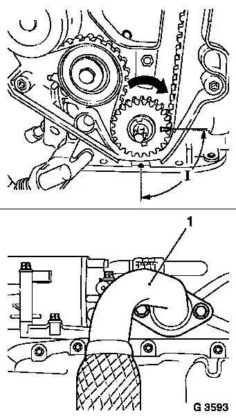
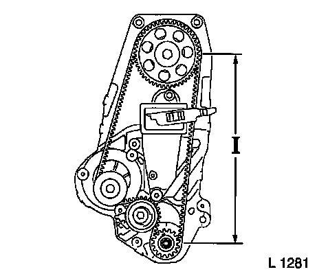
Screw fastening bolt for torsional vibration damper into
crankshaft and turn crankshaft in direction of engine rotation
90° (dimension I) in front of TDC mark.
Remove front exhaust pipe (1) – see operation "Centre
Muffler and Front Exhaust Pipe, Remove and Install" in group
"L".
|
|
|
Note: The drive unit
must be aligned to the front axle body using KM-6173 and KM-6001-A
in order to ensure correct alignment of the drive unit after
releasing the fastening bolts for the right and left engine damping
blocks. The attachment of KM-6173 and KM-6001-A is described in the
following.
 Install
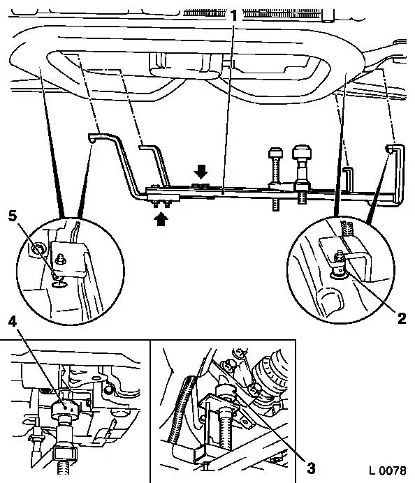
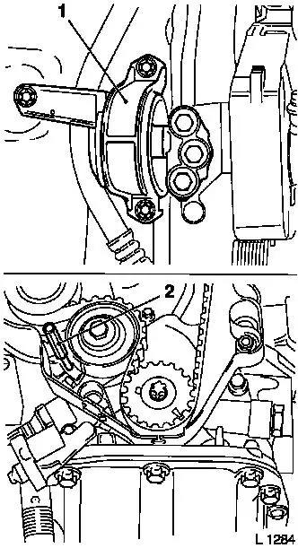
Attach KM-6173 (3) to front axle body – screw up support
bearing (2) until pin is seated flush in mount (1) on cylinder
block.
|
|
|
Release fastening bolts (arrows) for adjustment rails on
KM-6001-A (1).
Insert KM-6001-A as illustrated – pins (2) and (5) must
sit in guide holes of front axle body.
Tighten fastening bolts for adjustment rails.
Screw up front support bearing (4) and rear support bearing (3)
until contact is made with guide pins of front engine damping block
and rear engine damping block bracket – the guide pins must
seat free from play in the support bearings.
|
|
Remove
|
Detach or disconnect all wiring harness plugs, ground
connections and hose connections from intake manifold – see
operation "Intake Manifold, Remove and Install (X 16 SZR)" and
"Intake Manifold, Remove and Install (Z 16 SE)".
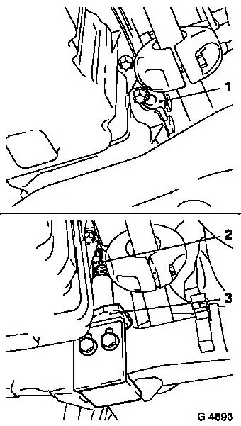
Detach wiring harness plug (1) from DIS ignition module and
expose wiring harness.
For X 16 SZR engine: Detach wiring trough (2) from camshaft
housing cover and lay aside.
Detach engine vent hose (3) from camshaft housing and engine
vent flange and remove.
Remove coolant hose (6) from thermostat housing.
For X 16 SZR engine: Detach preheater hose (5) from heat
shield.
For Z 16 SE engine: Detach ignition cable wiring trough from
camshaft housing cover.
Disconnect spark plug connectors.
Detach oxygen sensor wiring harness plug (4).
|
|
|
Remove right engine damping block (1) with engine damping block
bracket.
Move toothed belt tension roller upwards against spring force at
tension roller base plate until bore holes align. Fix toothed belt
tension roller in place with suitable drift (2).
Mark running direction of the toothed belt for identification
and remove toothed belt.
|
|
|
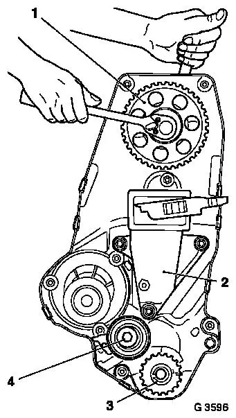
Detach toothed belt tension roller (4) from oil pump
housing.
Remove toothed belt drive gear (3) from crankshaft.
Remove engine damping block main bracket (2) from cylinder
block.
Remove camshaft housing cover from camshaft housing.
Remove camshaft pulley (1) – counterhold with op-ended
spanner on hex of camshaft.
|
|
|
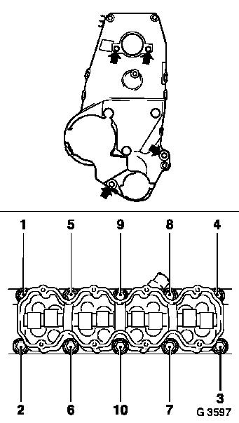
For X 16 SZR engine: Unclip cable for crankshaft pulse pick-up
from rear toothed belt cover.
Remove rear toothed belt cover (arrow) from oil pump housing and
camshaft housing.
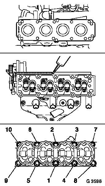
Detach cylinder head bolts in sequence shown. Remove camshaft
housing from cylinder head. Remove cam followers, thrust pieces and
hydraulic valve lifter – note layout. Remove cylinder head
from cylinder block.
 Clean Clean
Clean sealing surfaces, bore holes and thread of cylinder head
bolts.
 Inspect
Check cylinder head and cylinder block for plane surface –
see operations "Cylinder Head, Check for Plane Surface" and
"Cylinder Block, Check for Plane Surface".
|
|
Install
|
Install cylinder head gasket – mark "OBEN/TOP" on top and
towards timing side of engine.
Place cylinder head on cylinder block. Insert hydraulic valve
lifters, thrust pieces and cam followers with MoS 2 paste (grey) – note allocation.
Apply a bead of surface sealant (green) to sealing surfaces of
cylinder head.
Place camshaft housing on cylinder head.
Tighten cylinder head bolts in order shown – use torque
wrench and KM-470-B. Attach cylinder head and camshaft housing with
new cylinder head bolts to cylinder block – tightening torque
25 Nm / 18 lbf. ft. + 60° + 60° + 60°.
Attach rear toothed belt cover to oil pump and camshaft housing
– tightening torque 6 Nm / 4 lbf. ft.
|
|
For X 16 SZR engine: Clip cable for crankshaft pulse pick-up to
rear toothed belt cover – note cable routing.
Attach camshaft pulley to camshaft – counterhold with
op-ended spanner on hex of camshaft – tightening torque 45 Nm
/ 33 lbf. ft.
Install camshaft housing cover at camshaft housing –
tightening torque 8 Nm / 6 lbf. ft.
Attach engine damping block support to cylinder block –
tightening torque 50 Nm / 37 lbf. ft.
Slide toothed belt drive gear onto crankshaft journal –
note installation position.
Attach toothed belt tension roller to oil pump housing –
tightening torque 20 Nm / 15 lbf. ft.
|
Install toothed belt – ensure that tensioned side (I) is
taut.
Note timing marks! – see operation "Timing, Adjust".
Adjust toothed belt tension – see operation "Toothed Belt
Tension, Adjust".
Attach engine damping block to right of side member –
tightening torque 35 Nm / 26 lbf. ft.
Attach engine damping block bracket to auxiliary engine damping
blocks support – tightening torque 55 Nm / 41 lbf. ft.
|
|
Install lower part of toothed belt cover – see operation
"Toothed Belt Cover – Lower Part, Remove and Install".
Install ribbed V-belt tensioner – see operation "Ribbed
V-belt Tensioner, Remove and Install".
Connect wiring harness plug for oxygen sensor.
For Z 16 SE engine: Attach ignition cable wiring trough to
camshaft housing – tightening torque 8 Nm / 6 lbf. ft.
Connect spark plug connectors to spark plugs.
For X 16 SZR engine: Detach preheater hose from heat shield.
Attach coolant hose to thermostat housing.
Attach engine vent hose to camshaft housing and engine vent
flange.
For X 16 SZR engine: Attach wiring trough to camshaft housing
cover – tightening torque 8 Nm / 6 lbf. ft.
Connect wiring harness plug to DIS ignition module – note
cable routing.
Attach engine bleeding hose to camshaft housing cover.
Attach or connect all wiring harness plugs, ground connections
and hose connections to intake manifold – see operation
"Intake Manifold, Remove and Install (X 16 SZR)" and "Intake
Manifold, Remove and Install (Z 16 SE)".
Remove
Remove Mount KM-6001-A and KM-6173.
Install
Install front exhaust pipe – see operation "Centre Muffler
and Front Exhaust Pipe, Remove and Install" in group "L".
For version with hex bolts: Attach front exhaust pipe with new
gasket and bolts coated with assembly paste (white) to exhaust
manifold – tightening torque 35 Nm / 26 lbf. ft.
For version with hex nuts: Attach front exhaust pipe with new
gasket and new nuts to exhaust manifold – tightening torque
45 Nm / 33 lbf. ft.
Close coolant drain bolt.
Attach alternator to alternator shackle – tightening
torque 20 Nm / 15 lbf. ft.
Attach alternator support to alternator and intake manifold
– tightening torque 20 Nm / 15 lbf. ft.
Install ribbed V-belt – see operation "Ribbed V-belt,
Remove and Install".
Install upper part of toothed belt cover – see operation
"Toothed Belt Cover – Upper Part, Remove and Install".
Install air cleaner housing with air intake cover – see
illustration "Air Ducts (X 16 SZR)" and illustration "Air Ducts (Z
16 SE)".
Connect ground cable to battery.
Inspect
Charge cooling system – see operations "Cooling System,
Charge and Bleed" and "Cooling System, Check for Leaks".
|
