|
Multi-plate Clutch C1 and C2, Disassemble and
Reassemble (AF 20)
Survey
|
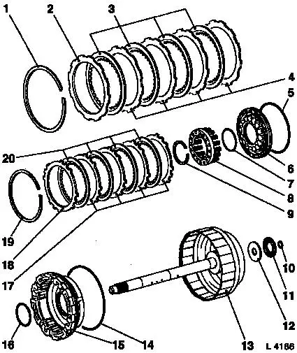
1
|
Retaining ring
|
|
2
|
Flange C1
|
|
3
|
Lining plates C1
|
|
4
|
Steel plates C1
|
|
5
|
O-ring
|
|
6
|
Piston C2
|
|
7
|
O-ring
|
|
8
|
Return spring assembly
|
|
9
|
Retaining ring
|
|
10
|
Seal ring
|
|
11
|
Thrust bearing
|
|
12
|
Race
|
|
13
|
Drive shaft
|
|
14
|
O-ring
|
|
15
|
Piston C1
|
|
16
|
O-ring
|
|
17
|
Steel plates C2
|
|
18
|
Flange C2
|
|
19
|
Retaining ring
|
|
20
|
Lining plates C2
|
|
|
 Remove Remove
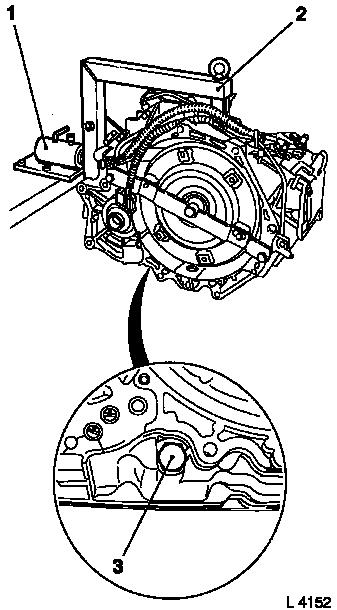
Remove transmission – see operation "Transmission, Remove
and Install (AF 20)". Secure converter against falling out.
|
Attach transmission to KM-694-A (2). Attach assembly to KM-113-2
(1).
Remove fluid drain bolt (3), drain transmission fluid and
collect for damage diagnosis – see operation "Transmission
Fluid Condition, Check (AF 13-II/AF 17/AF 20/AF 22)".
Remove converter – see operation "Converter and/or Fluid
Pump Seal Ring, Replace (AF 13-II/AF 17/AF 20/AF 22)".
Remove rear cover – see operation "Rear Cover with Piston
C1, Remove and Install (AF 20)".
|
|
Remove drive shaft assembly with multi-plate clutch C1 and C2
– see operation "Drive Shaft Assembly with Multi-plate Clutch
C1 and C2, Remove and Install (AF 20)".
 Inspect
|
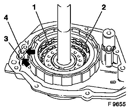
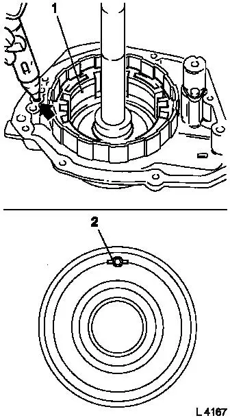
Check piston of multi-plate clutch C1 (1): Fit drive shaft onto
rear housing cover. Seal rings on rear cover and on rear side of
drive shaft must still be fitted. Blow in low-pressure compressed
air (4 bar, arrow 3); for this, cut off the end of KM-994 in
advance and insert KM-994 into bore hole. Ensure free passage of
piston.
Check piston of multi-plate clutch C1 (2): Fit drive shaft onto
rear housing cover. Seal rings on rear cover and on rear side of
drive shaft must still be fitted. Blow in low-pressure compressed
air (4 bar, arrow 4); for this, cut off the end of KM-994 in
advance and insert KM-994 into bore hole. Ensure free passage of
piston.
|
|
 Disassemble
|
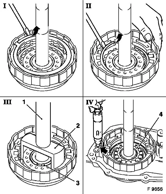
I
|
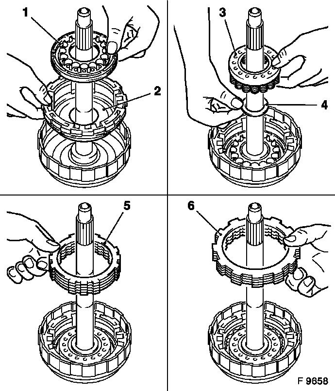
Disassemble multi-plate clutch C1: Lever out retaining ring
using screwdriver. Remove flange, lining plates and steel
plates.
|
|
II
|
Disassemble multi-plate clutch C2: Lever out retaining ring
using screwdriver. Remove flange, lining plates and steel
plates.
|
|
III
|
Remove return spring assembly: Place KM-698 (2) with KM-514 (1)
and KM-697 or KM-311-1 onto spring plate and compress under a
press. Release retaining ring (3) using KM-396.
|
|
IV
|
Remove piston (4) for multi-plate clutch C2: Fit drive shaft
assembly onto rear housing cover. Blow in low-pressure compressed
air (4 bar, arrow) and remove piston – assist with pliers, if
necessary. Replace O-rings for piston.
|
|
|
Remove
|
Remove piston (1) for multi-plate clutch C1: Fit drive shaft
assembly onto rear housing cover. Blow in low-pressure compressed
air (4 bar, arrow); for this, cut off the end of KM-994 in advance
and insert KM-994 into bore hole. Remove piston – assist with
pliers, if necessary. Replace O-rings for piston.
Inspect
Check sliding surfaces of steel and lining plates for damage and
wear. Replace if necessary. New lining plates must be laid in
transmission fluid for at least 2 hours before installation.
Check lock ball (2) of piston for multi-plate clutch C2: Check
if lock ball is free to move by shaking. Check whether valve leaks
with low-pressure air.
|
|
 Assemble
|
Insert piston (2) for multi-plate clutch C1 into drive shaft.
Insert piston (1) for multi-plate clutch C2 into drive shaft. Place
return spring assembly (3) with thrust washer (4) onto piston C1.
Compress return spring assembly with KM-698 and KM-514, KM-697 or
KM-311-1 under press and insert new retaining ring with KM-396.
Alternately each time, place steel plate (first), lining plate
and finally flange (5) (surface with rounded edge points to lining
plate) onto piston C2. Insert retaining ring using screwdriver.
Alternately each time, place steel plate (first), lining plate
and finally flange (6) (surface with rounded edge points to lining
plate) onto piston C1. Insert retaining ring using screwdriver.
|
|
 Measure
|
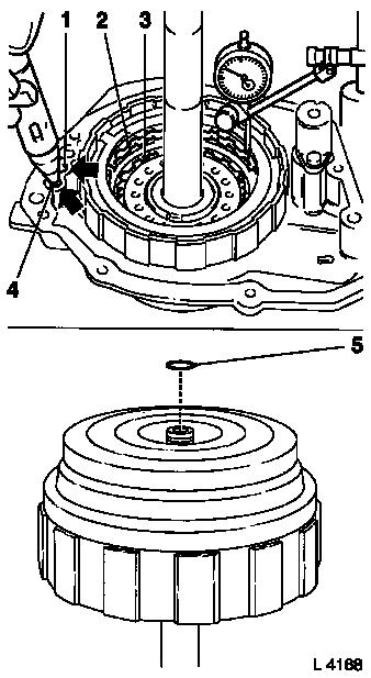
Measure piston stroke of multi-plate clutch C1: Fit drive shaft
into rear cover, blow low-pressure compressed air into bore hole on
rear cover (4 bar, arrow 4); for this, cut off the end of KM-994 in
advance and insert KM-994 into bore hole. Place probe of dial gauge
onto the top lining plate (3). If necessary, correct piston stroke
by installing a suitable compensation flange from the "Aftersales"
division. Measurement value: 1.52 to 1.89 mm.
Measure piston stroke of multi-plate clutch C2: Fit drive shaft
into rear cover, blow low-pressure compressed air into bore hole on
rear cover (4 bar, arrow 1) – for this, cut off the end of
KM-994 in advance and insert KM-994 into bore hole. Place probe of
dial gauge onto flange of multi-plate clutch C2 (2). Measurement
value: 1.52 to 1.89 mm.
 Install
Note O-ring (5). Install drive shaft assembly with multi-plate
clutches C1 and C2 – see operation "Drive shaft Assembly with
Multi-Plate Clutches C1 and C2, Remove and Install (AF 20)".
|
|
Install rear cover – see operation "Rear Cover with Piston
C1, Remove and Install (AF 20)".
Install converter – see operation "Converter and/or Fluid
Pump Seal Ring, Replace (AF 13-II/AF 17/AF 20/AF 22)". Secure
converter against falling out.
|
Attach fluid drain bolt (3) with new seal ring to transmission
– tightening torque 40 Nm / 29.5 lbf. ft.
Remove transmission assembly from KM-113-2 (1) with KM-694-A.
Remove transmission from KM-694-A (2).
Install transmission – see operation "Transmission, Remove
and Install (AF 20)". Fill up transmission fluid
Inspect
Check and correct level of transmission fluid – see
operation "Transmission Fluid Level, Check and Correct (AF 13-II/AF
17/AF 20/AF 22)".
|
|
|
