|
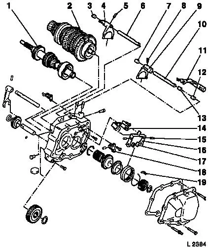
End Shield, Dismantle and Assemble (F18)
Illustration
|
1
|
Drive shaft
|
|
2
|
Main shaft
|
|
3
|
Teflon bushing
|
|
4
|
1st/2nd gear shift fork
|
|
5
|
Roll pin
|
|
6
|
1st/2nd gear shift rod
|
|
7
|
Teflon bushing
|
|
8
|
Roll pin
|
|
9
|
3rd/4th gear shift fork
|
|
10
|
3rd/4th gear shift rod
|
|
|
Illustration
|
11
|
5th gear shift driver
|
|
12
|
Teflon bushing
|
|
13
|
Teflon bushing
|
|
14
|
Bearing support
|
|
15
|
Pin
|
|
16
|
Rocker arm
|
|
17
|
Crosshead shoe
|
|
18
|
Bridge with locking pin
|
|
19
|
Sliding block
|
|
|
Illustration
|
20
|
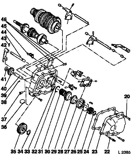
Fastening bolt M8
|
|
21
|
Fastening bolt M7
|
|
22
|
Fastening bolt
|
|
23
|
End shield cover
|
|
24
|
Gasket
|
|
25
|
Retaining ring
|
|
26
|
5th gear synchromesh body
|
|
27
|
Synchroniser spring
|
|
28
|
5th gear shift sleeve
|
|
29
|
5th gear synchroniser ring
|
|
|
Illustration
|
30
|
5th gear (driven)
|
|
31
|
Needle bearing
|
|
32
|
Retaining ring
|
|
33
|
Thrust washer
|
|
34
|
Retaining ring
|
|
35
|
5th gear (driving)
|
|
36
|
Magnet
|
|
37
|
Locking plugs
|
|
|
Illustration
|
38
|
Ball
|
|
39
|
Reverse gear shaft
|
|
40
|
Reverse gear
|
|
41
|
Thrust washer
|
|
42
|
Reverse gear shift fork
|
|
43
|
Roll pin
|
|
44
|
Reverse gear shift rod
|
|
45
|
Pawl
|
|
46
|
Locking plugs
|
|
|
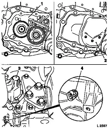
Note: Transmission
remains installed.
 Remove Remove
|
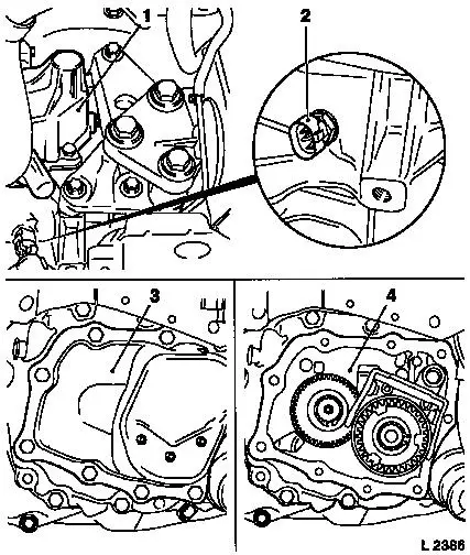
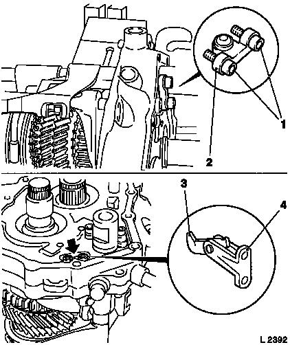
Remove gearshift cover (1) – see operation "Gearshift
Cover, Remove and Install and/or Seal (F13/F17/F17+/F18)".
Remove reversing lamps switch (2).
Remove end shield cover (3) – see operation "Gasket for
End Shield, Replace (F13/F17/F17+/F18)".
Remove end shield (4) from transmission – see operation
"Gasket for End Shield, Replace (F13/F17/F17+/F18)".
|
|
 Install
|
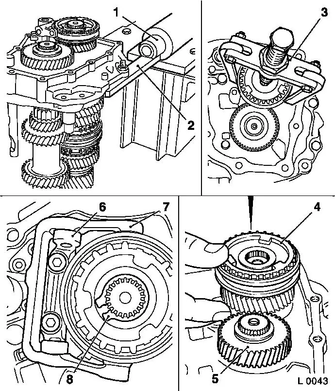
Attach end shield to KM-552 (2). Attach KM-552 to KM-113-2
(1).
Remove
Remove bearing support (6) with rocker arm (7) from end shield
(2 fastening bolts). Note installation position of crosshead
shoes.
Caution
Micro-encapsulated fastening bolts. If fastening bolts are
stiff, heat end shield with hot-air dryer to approx. 80 °C.
 Disassemble
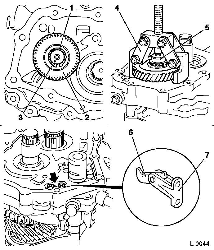
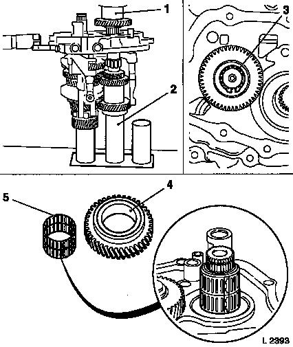
Remove retaining ring (8) from synchromesh body. Remove 5th gear
(4) synchromesh body with 5th gear (5) (small) from main shaft, if
stiff use KM-161-B (3). Remove both needle cages for 5th gear.
|
|
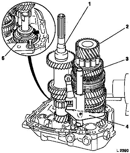
Disassemble
|
Remove retaining ring (1) of 5th gear (driving) (2) from drive
shaft (3).
Place thrust piece (5) for KM-553-A (4) on drive shaft. Remove
5th gear (driving) from drive shaft with KM-553-A. Ensure correct
seating of KM-553-A on 5th gear (driving).
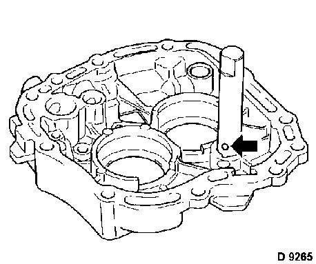
Remove bearing support (7) with rocker arm (6) from end shield
– 2 fastening bolts (arrow).
|
|
Caution
Micro-encapsulated fastening bolts. If fastening bolts are
stiff, heat end shield with hot-air dryer to approx. 80 °C.
Disassemble
|
Remove locking plugs (arrows) with KM-727-B (2) and KM-328-B (1)
from end shield.
Remove (3) fastening bolts (4) of bridge for locking pin from
end shield.
|
|
Caution
Micro-encapsulated fastening bolts. If fastening bolts are
stiff, heat end shield with hot-air dryer to approx. 80 °C.
Disassemble
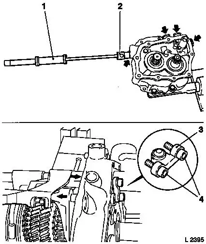
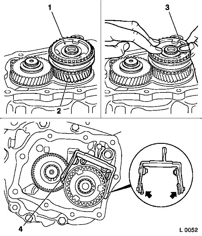
Engage 2nd and 5th gears (with shift driver). If 3rd gear is now
engaged, the bridge will be pushed out.
|
Note: Relieve
pressure on all shifter rod guides – for this, support
shifter rods as shown above with wood (1).
|
|
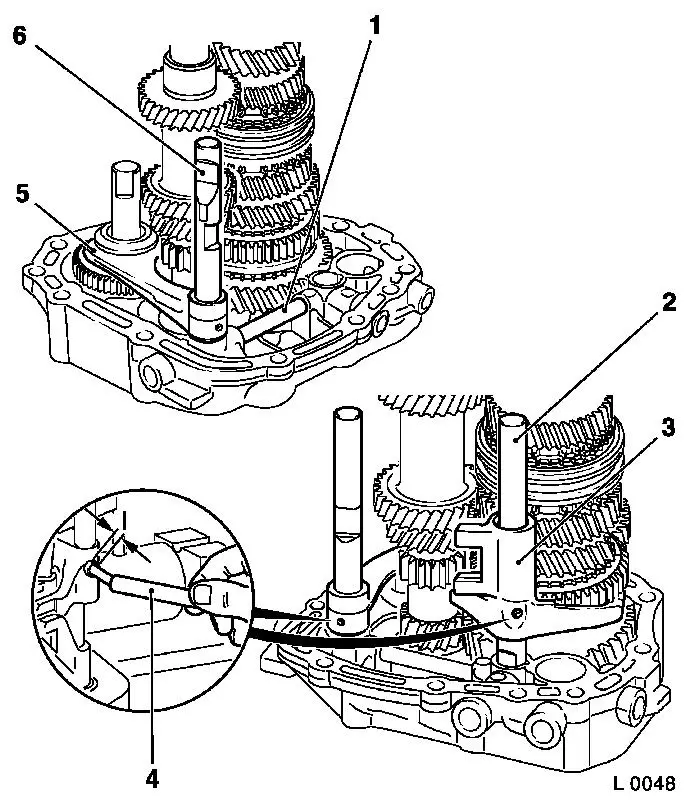
Disassemble
Drive coiled pins (arrows) out of 3rd / 4th gear shift fork (3)
and reverse shift fork (6) using KM-308.
Remove 3rd, 4th (3) and reverse gear (6) shifter rods (2) and
shift forks from end shield.
Remove 5th gear shift driver (4) from end shield.
Remove locking pin (5) for catch from end shield bore holes.
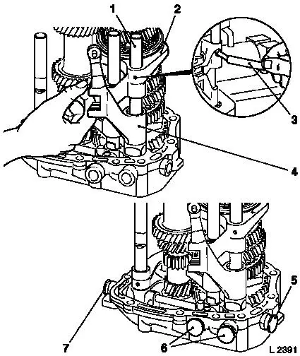
Disassemble
|
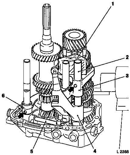
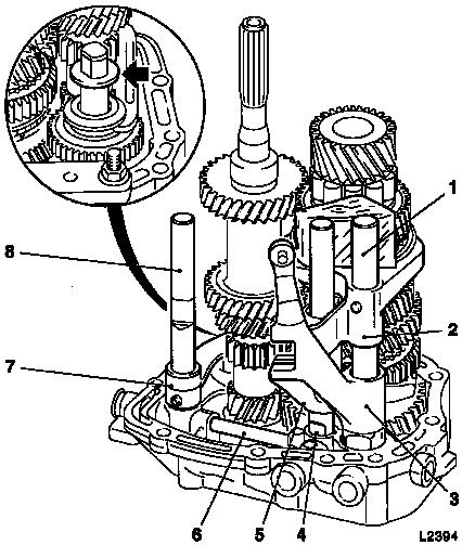
Tension retaining rings for main shaft (2) and drive shaft (5)
with KM-443-B. As assembly aid, keep retaining ring for main shaft
(2) under tension with Installation Plate KM-443-1 (1).
Tension retaining ring for drive shaft (5) with KM-396 (6).
Lift main shaft (2), drive shaft (5) and reverse gear wheel
together, until retaining ring of drive shaft (5) springs out of
groove in bearing.
Remove main shaft (2), drive shaft (5), reverse gear wheel (8)
and shift fork (4) with 1st / 2nd gear shifter rod (3) together
from end shield.
|
|
Note: Clamp reverse
gear (7) in vice with protective jaws. Carefully knock off end
shield with brass punch.
 Clean Clean
Clean all parts and sealing surfaces.
 Inspect
Check parts for wear, signs of scoring, damage; if necessary
replace.
Lubricate rotating parts on their bearing, running, seating, and
pressure surfaces using transmission fluid.
Install
|
Press reverse gear axle with inserted lock ball (arrow) to start
in end shield.
Caution
Note installation position.
|
|
 Assemble
Coat bearing and reverse bore hole with transmission fluid.
|
Tension new retaining ring for main shaft (2) with KM-443-B and
keep under tension with KM-443-1. Insert new retaining ring for
drive shaft (1) into groove in end shield.
Insert main shaft (2), drive shaft (1), reverse gear wheel (5)
and shift fork (4) with 1st / 2nd gear shifter rod (3) into end
shield. Tension retaining ring for drive shaft with retaining ring
pliers, until retaining ring slides over the bearing.
|
|
Note: Retaining rings
must engage correctly into grooves. Shift fork groove (arrow) for
reverse gear wheel (5) points upwards.
Note: To relieve
pressure on shift rod guides in end shield, support shift rods with
wooden wedge when securing with pin.
Assemble
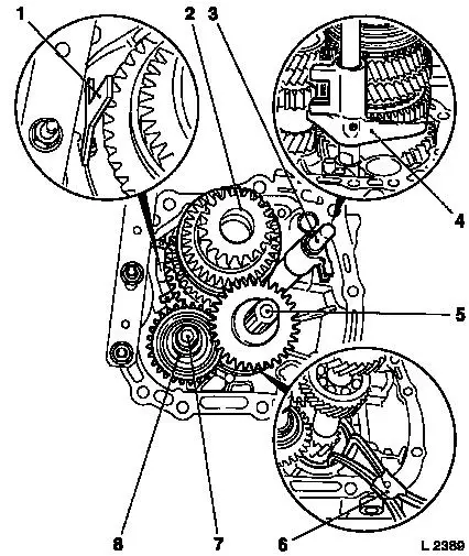
|
Insert locking pin (1) reverse gear 3rd/4th.
Allow new coiled pin to protrude approx. 2 mm (dimension I).
Insert shift fork (5) and reverse gear shifter rod (6) and pin with
KM-308 (4).
Insert shift fork (3) and shift rod (2) for 1st/2nd gear and
insert pin with KM-308 (4).
|
|
Note: In order to
relieve pressure on shifter rod guide in end shield, support
shifter rods when pinning with wooden wedge.
Assemble
|
Insert 5th gear (4) shift driver.
Insert shift fork (2) and shift rod for 3rd/4th gear (1) and Pin
KM-308 (3).
Fit four detent pins (5/6/7) and drive to stop with plastic
hammer or soft metal drift.
Bring shift fork into neutral speed position.
|
|
Assemble
Engage 2nd/3rd/5th gear.
|
Coat new fastening bolts (1) with locking compound.
Position bridge (2) for locking pin on end shield and lightly
tighten with fastening bolts. Switch 1st/2nd gear shift fork to
neutral. Attach bridge fastening bolts – tightening torque 7
Nm / 5 lbf. ft.
Bring shift fork into neutral speed position.
Coat new fastening bolts (arrow) with locking compound.
Attach bearing support (4) with pawl (3) to end shield (2
fastening bolts) – tightening torque 7 Nm / 5 lbf. ft.
|
|
Assemble
|
Remove end shield from KM-113-2 with KM-552. Insert end shield
with main and drive shaft into KM-554 (2).
Press on gearwheel for 5th gear (driving) with KM-514 (1).
Caution
Collar of gearwheel points to end shield. Fit new retaining ring
(3).
Assemble
Insert both thrust washers and secure with retaining ring.
Attach end shield to KM-113-2 with KM-552.
Coat needle bearing (5) for gear wheel of 5th gear (4) with
transmission fluid and place on main shaft. In doing so, ensure
correct seating of needle bearing.
|
|
Assemble
Coat seating surfaces of main shaft and synchromesh body with
transmission fluid.
|
Slide 5th gear (2) and synchromesh body (1) onto main shaft and
secure with new retaining ring (3).
Insert crosshead shoes (arrows) into 5th gear shift fork
(4).
After assembly, insert 5th gear and check whether crosshead
shoes at top and bottom on synchromesh body has a slight degree of
play. Possibly turn crosshead shoes by 180° or exchange.
Coat new fastening bolts with locking compound.
Attach bearing bracket with rocker arm to end shield (2
fastening bolts) – tightening torque 22 Nm / 16 lbf. ft.
|
|
Install
|
Fit friction washer (arrow) on reverse gear axle.
Cement friction washer with grease.
Caution
Before installation of transmission
unit check following items for position and seating.
|
1
|
3rd/4th gear shift rod
|
|
2
|
3rd/4th gear shift rod
|
|
3
|
5th gear shift driver
|
|
4
|
1st/2nd gear shift rod
|
|
5
|
1st/2nd gear shift fork
|
|
6
|
Lock pin for gear stop
|
|
7
|
Reverse gear shift fork
|
|
8
|
Reverse gear shift rod
|
|
|
Install
|
Insert end shield (1) into transmission – see operation
"Gasket for End Shield, Replace – F13/F17/F17+/F18".
Install gasket for end shield cover (2) – see operation
"Gasket for End Shield Cover, Replace –
F13/F17/F17+/F18".
Install reversing lamps switch (4) with new seal ring –
tightening torque 20 Nm / 15 lbf. ft.
Install gearshift cover (3) – see operation "Gearshift
Cover, Remove and Install and/or Seal (F13/F17/F17+/F18)".
|
|
Inspect
Check transmission fluid level – see operation
"Transmission Fluid Level, Check and Correct
(F13/F17/F17+/F18)".
|
