|
Change-Over Valve Housing, Remove and Install
Important: When
working on the fuel system it is essential to pay attention to
cleanliness as even the smallest dirt particles can lead to faults
in engine operation or in the fuel system. Open fuel connections
must be sealed with appropriate plugs from the Opel Parts Catalogue
(catalogue number: 45 06 154 / part number: 9201697). Sealing plugs
are only intended to be used once.
 Remove Remove
| 2. |
Disconnect battery
| • |
Detach earth connection from earth terminal
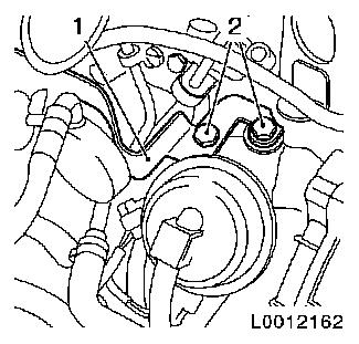
|
|
| 3. |
Raise vehicle by its full height
|
| 4. |
Detach the lower engine cover and right engine splash guard
|
| 5. |
Place collecting basin underneath.
|
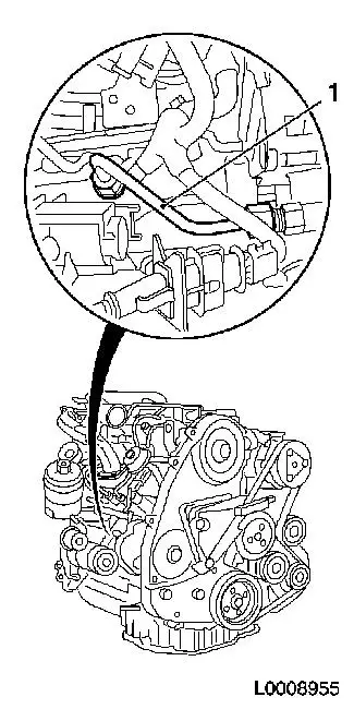
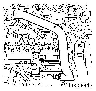
Important: After detaching the
pressure line, seal off high pressure pump and pressure chamber
openings with protective caps
1)
|
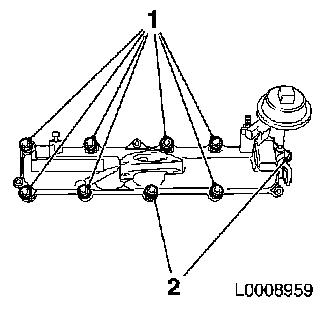
| 6. |
Remove high pressure line (1) from high pressure pump to
pressure chamber
| • |
Unscrew 2x union nuts
| – |
From pressure chamber with KM-812
|
| – |
From high pressure pump with KM-6098
|
|
| • |
Seal 2x opening with protective cap
|
|
|
|
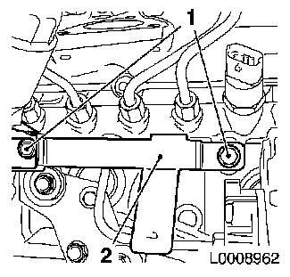
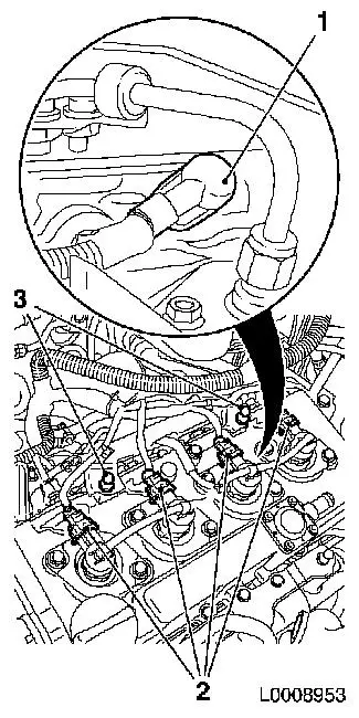
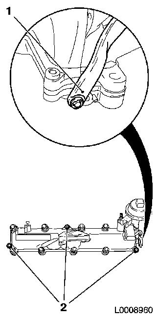
| 7. |
Detach wiring harness bracket (2) from pressure chamber
|
|
|
| 8. |
Lower vehicle by its full height
|
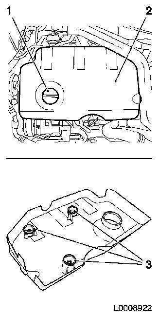
| 9. |
Remove engine cover (2)
| • |
Detach oil filler port closure cap (1)
|
| • |
Pull off engine cover
Note: Rubber retainers
(3) must remain on engine cover
|
| • |
Attach oil filler port closure cap
|
|
|
|
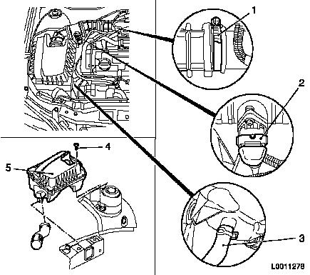
| 10. |
Remove air cleaner housing (5) with air intake hose
| • |
Detach wiring harness plug (2) from hot film mass air flow
meter
|
| • |
Detach air intake hose from air intake pipe
|
| • |
Detach air cleaner housing from wheel housing
|
| • |
Detach water drain hose (3) from air cleaner housing
|
|
|
|
| 11. |
Remove air intake manifold (1)
|
|
|
| 12. |
Detach wiring harness for injectors
| • |
Disconnect 4x wiring harness plugs for injector (2)
|
| • |
Disconnect 4x wiring harness plug for glow plug (1) with KM-717
|
| • |
Push wiring harness to one side
|
|
|
|
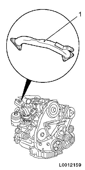
| 13. |
Remove charge air pipe (1)
|
|
|
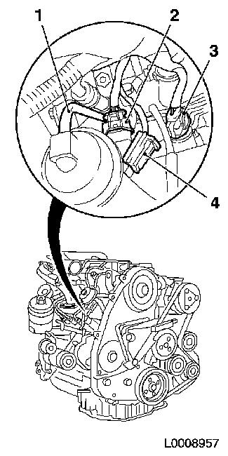
| 14. |
Disconnect wiring harness plug (3) from pressure sensor
|
| 15. |
Disconnect wiring harness plug (4) from vacuum unit change-over
valves
|
| 16. |
Detach vacuum line (1) from vacuum unit change-over valves
|
| 17. |
Disconnect wiring harness plug (2) from charge pressure
sensor
|
|
|
| 18. |
Detach bracket, fuel damping unit (1)
| • |
Unscrew 2x nuts (2)
Note: Tie bracket, fuel
damping unit, with fuel line and damping unit, to bulkhead
|
|
|
|
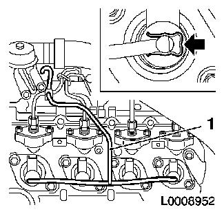
Important: After detaching the
pressure lines, seal the apertures of the injectors and the
pressure chamber with protective caps
1)
|
| 19. |
Remove high pressure lines (1), pressure chamber to
injectors
| • |
Unscrew 8x union nut with KM-812 or
KM-6098
|
| • |
Take out pressure lines
|
| • |
Seal 4x pressure chamber opening with protective cap
|
| • |
Seal 4x injector opening with protective cap
|
|
|
|
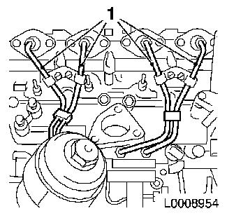
| 20. |
Detach fuel return line (1)
| • |
Detach 4x fuel return line from injector
| – |
Press 4x retaining clamps in direction of arrow
|
|
| • |
Detach fuel return line from pressure chamber
|
| • |
Unscrew 2x bolts
Note: Note different
bolt lengths
|
|
|
|
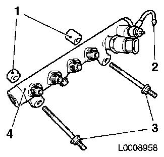
| 21. |
Remove pressure chamber (4)
| • |
Detach fuel return line from connection (2)
|
| • |
Unscrew 2x bolts
Note: Note different
lengths of the bolt (3) and spacer sleeves (1)
|
|
|
|
| 22. |
Remove intake manifold
|
|
|
| 23. |
Detach change-over valve housing from intake manifold
| • |
Detach linkage (1) from change-over valve lever
|
|
|
|
 Install
| 24. |
Clean sealing surfaces.
| • |
Change-over valve housing and intake manifold
|
|
| 25. |
Attach change-over valve solenoid valve to intake manifold
| • |
Attach linkage to change-over valve lever
|
|
| 26. |
Install intake manifold
|
| 27. |
Install accumulator
Note: Note different
lengths of the bolt and spacer sleeves
| • |
Attach fuel return line
| – |
From high pressure pump to pressure chamber
|
|
|
| 28. |
Install fuel return line
Note: Note different
bolt lengths
| • |
Attach 4x fuel return line to injector
|
| • |
Attach fuel return line to accumulator
|
|
| 29. |
Install 4x high-pressure lines from pressure chamber to
injectors
| • |
Fit 8x union nuts finger-tight
|
|
| 30. |
Fasten pressure chamber
|
| 31. |
Fasten high pressure lines of pressure chamber to injectors
| • |
Tighten 8x union nut with KM-812 or
KM-6098 25
Nm
Note: Tighten union
nuts first at injectors, then at pressure chamber
|
|
| 32. |
Attach bracket, fuel damping unit
|
| 33. |
Connect wiring harness plug to pressure sensor
|
| 34. |
Connect wiring harness plug to vacuum unit change-over
valve
|
| 35. |
Attach vacuum line to vacuum unit change-over valve
|
| 36. |
Connect wiring harness plug to charge pressure sensor
|
| 38. |
Attach wiring harness for injectors
| • |
Connect 4x wiring harness plugs, glow plug
|
| • |
Connect 4x injector wiring harness plug
|
|
| 39. |
Install air intake pipe.
|
| 40. |
Install air cleaner housing with air intake hose
| • |
Attach water drain hose to air cleaner housing
|
| • |
Attach air intake hose to air intake pipe
|
| • |
Connect wiring harness plug to air mass flow meter
|
|
| 41. |
Install engine cover
| • |
Detach oil filler port closure cap
|
| • |
Attach oil filler port closure cap
|
|
| 42. |
Raise vehicle by its full height
|
| 43. |
Attach wiring harness bracket to pressure chamber
|
| 44. |
Install high pressure line from high pressure pump to
accumulator
| • |
Insert high pressure line
|
| • |
Tighten 2x union nut with KM-812 or
KM-6098 25
Nm
|
|
| 45. |
Install lower engine cover and right engine splash guard
|
| 46. |
Lower vehicle by its full height
|
| 47. |
Connect battery
| • |
Attach earth connection to earth terminal
|
|
Important: Wear protective
goggles
|
| 48. |
Carry out leak test on high pressure system
Note: Engine must be at
operating temperature
| • |
Carry out actuator test (fuel leak)
|
| • |
Visual inspection of high pressure system for fuel leak
|
|
| 49. |
Program volatile memories
|
1 ) Protective caps are available from the Opel
parts catalogue under catalogue number 45 06 154 / part number:
9201697
|
