Piston, Connecting Rod, and Bearing Replacement
Special Tools
EN-46785 Fixing Tool
For equivalent regional tools, refer to
Special Tools .
Removal Procedure
| 4. |
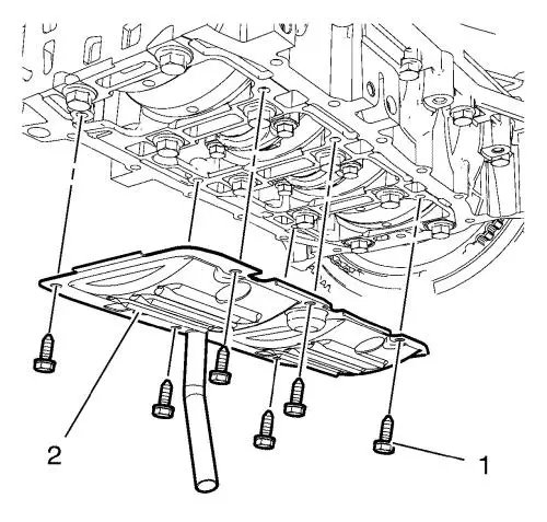
Remove the 6 oil pan baffle
bolts (1). |
| 5. |
Remove the oil pan baffle
(2). |
|
Note: If the
EN-46785 fixing tool is installed, remove it.
|
| 6. |
Set the crankshaft to TDC of
combustion stroke of cylinder 1. |
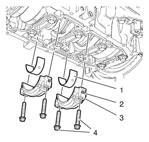
| 7. |
Remove and DISCARD the 4
connecting rod bearing cap bolts (4) from the cylinder 2 and
3. |
|
Note: Marking (2) of
the connecting rod bearing caps. Set aside in the order
removed.
|
|
Note: The shear
surfaces of the connecting rod and the connecting rod bearing cap
form a unique fit and must not be swapped or damaged. Do not lay
down on the shear surfaces.
|
| 8. |
Remove the 2 connecting rod
bearing caps (3) from the cylinder 2 and 3. |
|
Note: Set aside in
the order removed.
|
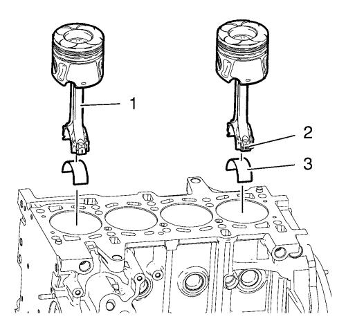
| 9. |
Remove the 2 connecting rod
lower bearings (1). |
|
Note: Marking (2) of
the connecting rod. Set aside in the order removed.
|
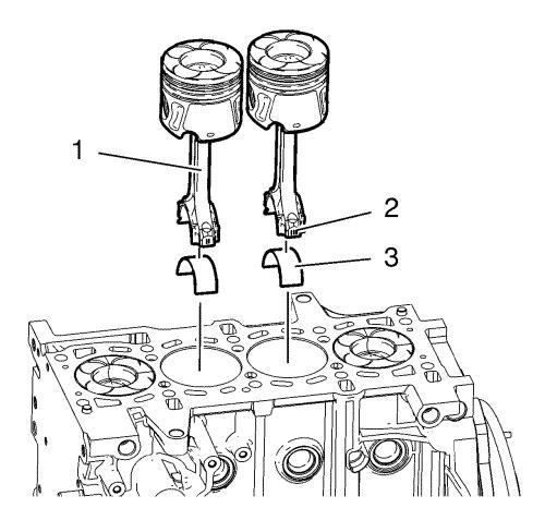
| 10. |
Push the 2 pistons with
connecting rod (1) from the cylinder 2 and 3 upwards. |
| 11. |
Remove the 2 connecting rod
upper bearings (1) from the cylinder 2 and 3. |
| 12. |
Turn the crankshaft through
180° and set crankshaft to TDC of combustion
stroke of cylinder 2. |
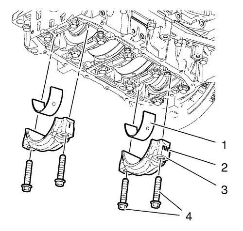
| 13. |
Remove and DISCARD the 4
connecting rod bearing cap bolts (4) from the cylinder 1 and
4. |
|
Note: Marking (2) of
the connecting rod bearing caps. Set aside in the order
removed.
|
|
Note: The shear
surfaces of the connecting rod and the connecting rod bearing cap
form a unique fit and must not be swapped or damaged. Do not lay
down on the shear surfaces.
|
| 14. |
Remove the 2 connecting rod
bearing caps (3) from the cylinder 1 and 4. |
|
Note: Set aside in
the order removed.
|
| 15. |
Remove the 2 connecting rod
lower bearings (1). |
|
Note: Marking (2) of
the connecting rod. Set aside in the order removed.
|
| 16. |
Push the 2 pistons with
connecting rod (1) from the cylinder 1 and 4 upwards. |
|
Note: Set aside in
the order removed.
|
| 17. |
Remove the 2 connecting rod
upper bearings (3) from the cylinder 1 and 4. |
Installation Procedure
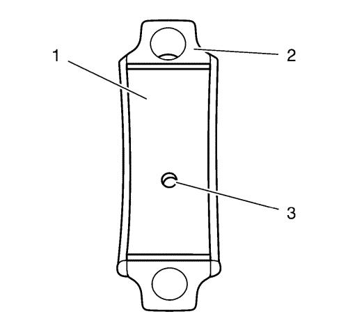
|
Note: Install the 4
connecting rod bearing shells with oil bore (3) into the connecting
bearing caps (2).
If the old connecting rod bearing shells will be reused,
install in their original position.
|
| 2. |
Install the 8 connecting rod
bearing shells (1). |
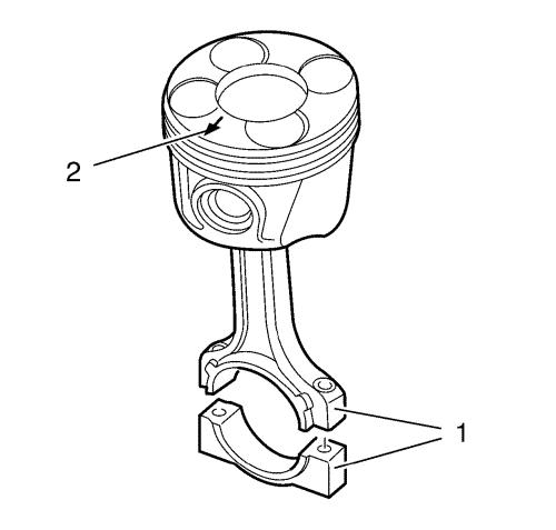
| 3. |
The arrow (2) on the piston
head must point to the timing side. |
|
Note: The connecting
rod bearing caps must be installed in their original position.
|
| 4. |
Note the marking (1) of the
connecting rod and connecting rod cap. |
| 5. |
The piston ring joints must be
displaced 120° to each other. |
| 6. |
Set the crankshaft to TDC of
combustion stroke of cylinder 2. |
| 7. |
Coat all pistons and cylinder
bores with engine oil. |
| 8. |
Install a piston ring
compressor in order to compress the piston rings. |
| 9. |
Install the 2 pistons with
connecting rod (1) and connecting rod upper bearing shells (3) into
cylinder 1 and 4. |
|
Note: Marking (2) of
the connecting rod bearing caps.
|
| 10. |
Install the 2 connecting rod
bearing caps (3) with connecting rod lower bearing shells (1) into
cylinder 1 and 4. |
| 11. |
Install 4 NEW connecting rod
bearing cap bolts (4) to cylinder 1 and 4 and tighten in following
order: |
| |
• |
Tighten the bolts in first
step to 20 N·m (15 lb ft) . |
| |
• |
Tighten the bolts to an
additional 40° . |
| 12. |
Turn the crankshaft through
180° and set crankshaft to TDC of combustion
stroke of cylinder 1. |
| 13. |
Install a piston ring
compressor in order to compress the piston rings. |
| 14. |
Install the 2 pistons with
connecting rod (1) with connecting rod upper bearing shells (3)
into cylinder 2 and 3. |
|
Note: Marking (2) of
the connecting rod bearing caps.
|
| 15. |
Install the 2 connecting rod
bearing caps (3) with the connecting rod lower bearing shells (1)
into cylinder 2 and 3. |
| 16. |
Install 4 NEW connecting rod
bearing cap bolts (4) to the cylinder 2 and 3 and tighten in
following order: |
| |
• |
Tighten the bolts in first
step to 20 N·m (15 lb ft) . |
| |
• |
Tighten the bolts to an
additional 40° . |
| 17. |
Install the oil pan baffle
(2). |
| 18. |
Install the 6 oil pan baffle
bolts (1) and tighten to 9 N·m (80 lb in)
. |
|
