Engine Replacement (1.4L LDD)
Special Tools
| • |
CH-49289
Centering Frame |
| • |
CH-49290
Engine Support Tool |
| • |
EN-34730-91
Pressure Tester |
For equivalent regional tools, refer to
Special Tools .
Removal Procedure
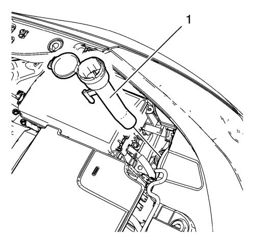
| 4. |
Remove the windshield washer
solvent container filler tube (1). |
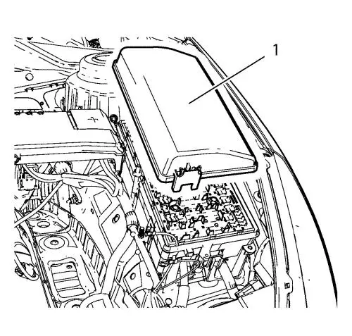
| 5. |
Remove the front compartment
fuse block cover (1). |
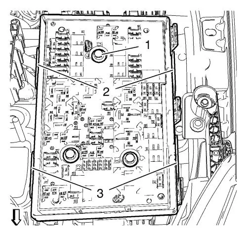
| 6. |
Loosen the 3 front compartment
fuse block bolts (1). |
| 7. |
Unclip the 4 front compartment
fuse block retainer clips (2) and (3) and lift the front
compartment fuse block slightly up. |
|
Note: The wiring
harness plugs should remain in the lower part (4) of the front
compartment fuse block.
|
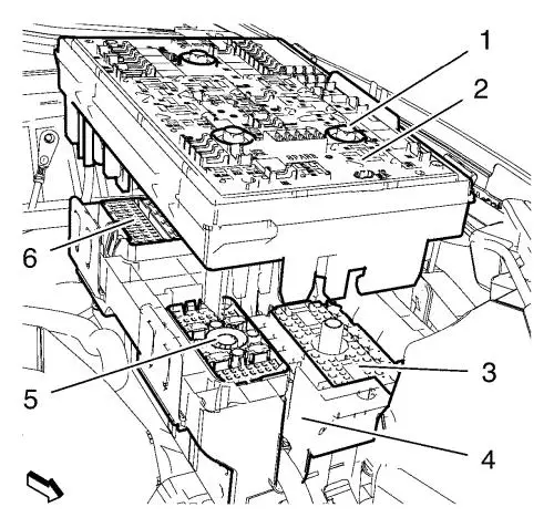
| 8. |
Entirely loosen the 3 front
compartment fuse block bolts (1) while lifting the front
compartment fuse block until it can be removed from the 3 wiring
harness plugs (3), (5) and (6). |
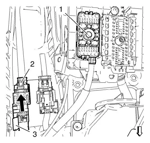
| 9. |
Remove the ECM wiring harness
plug (1) from the lower part of the front compartment fuse
block. |
| 10. |
Disconnect the ECM wiring
harness plug (2) and unclip it from retainer clip (3). |
| 11. |
Remove the 3 ground cable nuts
(1) and put the 3 ground cables (2) aside. |
| 12. |
Unclip the ECM wiring harness
from body. |
| 13. |
Unclip the back up lamp switch
wiring harness from body. |
| 20. |
Put the radiator surge tank
aside. |
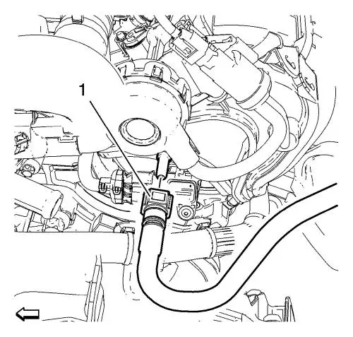
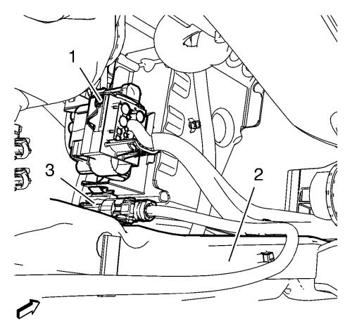
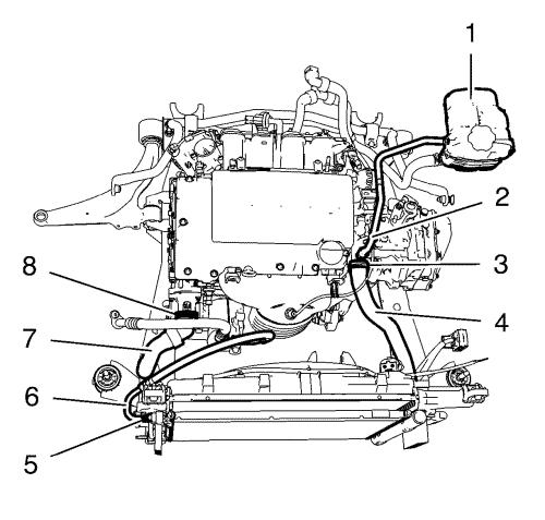
| 23. |
Disconnect the booster vacuum
pipe (1) from the intake manifold. |
| 24. |
Disconnect backup lamp switch
wiring harness electrical connector and unclip from retainer
clip. |
| 25. |
Place collecting basin
underneath the vehicle. |
|
Warning:
Gasoline or gasoline vapors are highly flammable.
A fire could occur if an ignition source is present. Never drain or
store gasoline or diesel fuel in an open container, due to the
possibility of fire or explosion. Have a dry chemical (Class B)
fire extinguisher nearby. |
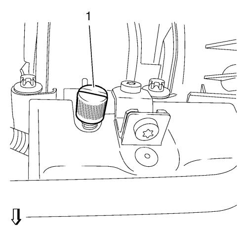
| 27. |
Remove fuel injector rail cap
(1). |
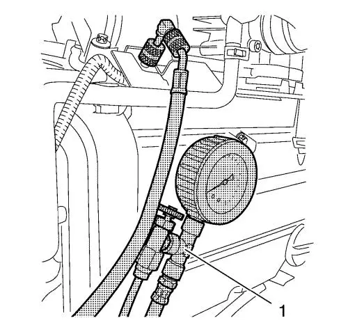
| 28. |
Relieve fuel pressure. Use
EN-34730-91 pressure tester (1). |
| 29. |
Remove fuel feed pipe (2) from
fuel injector rail. |
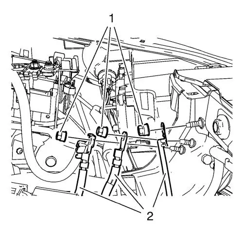
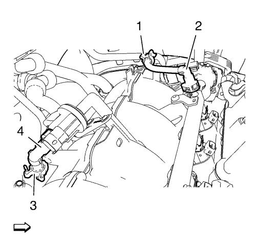
| 30. |
Unclip fuel feed pipe from
retainer clip (1). |
| 31. |
Remove fuel ventilation pipe
(4) from evaporative emission canister purge solenoid valve.
|
| 32. |
Unclip fuel ventilation pipe
from retainer clip (3). |
| 33. |
Close the vents with the
EN-6015 closure plugs . |
| 34. |
Remove the lower condenser
hose nut (3). |
| 35. |
Remove the lower condenser
hose (1) and the seal ring (2). |
| 36. |
Remove the A/C compressor and
condenser hose nut (1) from air conditioning evaporator
hose. |
| 37. |
Remove the A/C compressor and
condenser hose (2) and the seal ring (3) from air conditioning
evaporator hose. |
| 44. |
Disconnect the wheel speed
sensors on both sides and unclip from suspension frame.
|
| 45. |
Remove the wheel speed sensor
wiring harness retainers from the frame. |
| 46. |
Disconnect the engine coolant
fan wiring harness plug (1) an unclip from suspension frame
(2). |
| 47. |
Disconnect the EPS wiring
harness plug (3). |
| 48. |
Disconnect the EPS main wiring
harness plug from EPS unit. |
|
Note: The SPX
installation manual is supplied with the special tool and is also
available online from SPX directly. Go to
www.spxtools-shop.com.
|
| 50. |
Assemble the CH-49290
engine support tool (1) according to the details provided in
the SPX installation manual. |
| 51. |
Support the CH-904
base frame on a jack. |
| 52. |
Support the CH-49290
engine support tool on the CH-904 base frame
. |
|
Note: The SPX
installation manual is supplied with the special tool and is also
available online from SPX directly. Go to
www.spxtools-shop.com.
|
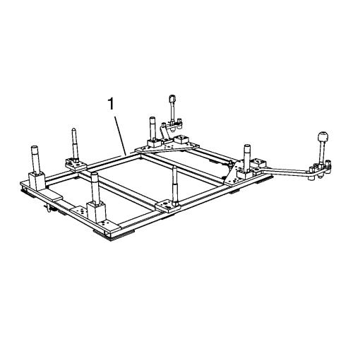
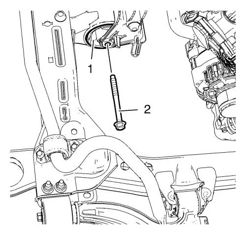
| 53. |
Install the CH-49290
engine support tool (1) according to the details provided in
the SPX installation manual. |
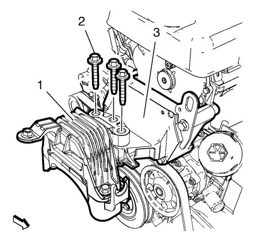
| 54. |
Remove the 3 engine mount
bolts (2) from the engine mount (1) and the engine mount bracket
(3). |
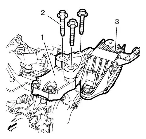
| 55. |
Remove the 3 transmission
mount bolts (2) from the transmission mount (3) and the
transmission mount bracket (1). |
|
Note: The SPX
installation manual is supplied with the special tool and is also
available online from SPX directly. Go to
www.spxtools-shop.com.
|
| 56. |
Assemble the CH-49289
centering frame (1) according to the details provided in the
SPX installation manual. |
| 57. |
Support the CH-904
base frame on a jack. |
| 58. |
Support the CH-49289
centring frame on the CH-904 base frame
. |
|
Note: The SPX
installation manual is supplied with the special tool and is also
available online from SPX directly. Go to
www.spxtools-shop.com.
|
| 59. |
Install the CH-49289
centering frame (1) according to the details provided in the
SPX installation manual. |
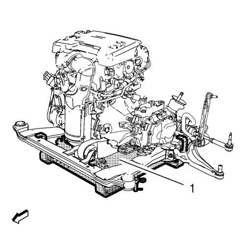
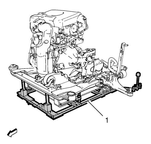
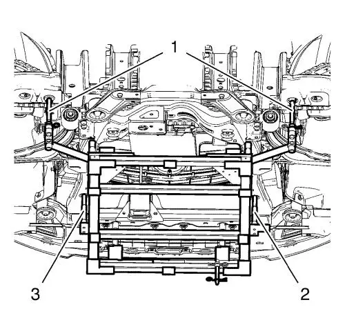
|
Note: Simplified
graphic. Engine/transmission unit is fixed with engine support tool
to suspension frame. Suspension frame is supported by centering
adapter and underframe.
|
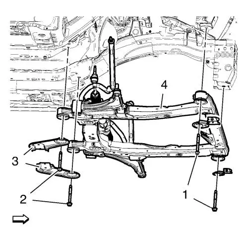
| 60. |
Remove the frame front bolts
(1). |
| 61. |
Remove the frame rear bolts
(2). |
| 62. |
Remove the frame
reinforcements (3). |
| 63. |
Lower suspension frame (4)
carefully with the engine transmission unit off the vehicle with
hydraulic jack about 7 cm (2.75 in) . |
| 64. |
Remove the 2 wiring harness
bracket bolts from EPS unit. |
| 65. |
Remove the 2 wiring harness
bracket from EPS unit. |
| 66. |
Remove suspension frame
carefully with the engine transmission unit from the vehicle with
hydraulic jack. |
| 69. |
Remove the engine coolant air
bleed hose (2) from water outlet. |
| 70. |
Remove the radiator surge tank
(1) in compound with the engine coolant air bleed hose.
|
| 71. |
Remove the A/C compressor and
condenser hose nut (5) from condenser. |
| 72. |
Remove the A/C compressor and
condenser hose (6) from condenser. |
| 73. |
Unlock the radiator coolant
feed hose quick connector (8) and remove the radiator coolant feed
hose (7) from engine coolant thermostat housing. |
| 74. |
Remove the radiator coolant
return hose clamp (3). |
| 75. |
Remove the radiator coolant
return hose (4) from water outlet. |
| 76. |
Remove the complete radiator
and condenser assembly from suspension frame. |
| 77. |
Install suitable cable at the
3 engine lift brackets. |
| 78. |
Install a suitable engine
lifting device to the cable. |
| 79. |
Extend the engine lifting
device until the steel cable are slightly tensioned. |
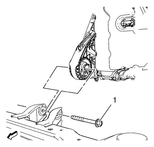
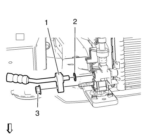
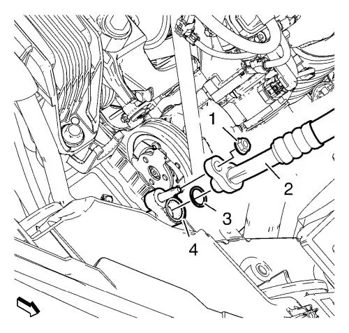
| 80. |
Remove the front transmission
mount through bolt (1). |
| 81. |
Remove the transmission
bracket mount to mount through bolt (1). |
| 82. |
Lower and remove the
frame. |
| 83. |
Put the engine transmission
unit down on a wooden pallet. |
|
Note: Second
technician required.
|
| 85. |
Remove the last 2 transmission
bolts and the transmission. |
| 86. |
Install the engine to suitable
engine stand. |
| 87. |
Transfer parts as
needed. |
Installation Procedure
| 1. |
Remove the engine from the
engine stand. |
| 2. |
Put the engine down on a
wooden pallet. |
|
Note: Second
technician required.
|
| 3. |
Install the transmission and 2
transmission bolts. |
| 4. |
Install the 6 transmission
bolts. |
| 6. |
Install suitable cable at the
3 engine lift brackets. Install a suitable engine lifting device to
the cable. Raise the engine transmission unit and extend the engine
lifting device until the steel cable are slightly tensioned.
|
| 7. |
Raise the CH-904
base frame and CH-49289 centring frame with
the hydraulic jack until it contacts the frame. |
| 8. |
Place the engine transmission
unit into the front frame. |
| 9. |
Install the rear transmission
bracket mount to mount through bolt (1) and tighten to 100
N·m (74 lb ft) . |
| 10. |
Install the front transmission
mount through bolt (1) and tighten to 100 N·m (74 lb
ft) . |
| 11. |
Remove the cable from the 3
engine lift brackets. |
| 12. |
Install the complete radiator
and condenser assembly to the suspension frame. |
| 13. |
Install the A/C condenser and
compressor hose (6) to condenser. |
| 14. |
Install the A/C condenser and
compressor hose nut and tighten to 19 N·m (14 lb
ft) . |
| 15. |
Install the radiator outlet
hose (7) to the thermostat housing and lock the quick connector
(8). |
| 16. |
Install the radiator inlet
hose (4) to the water outlet. |
| 17. |
Install the radiator inlet
hose clamp (3). |
| 18. |
Install the engine coolant air
bleed hose (2). |
| 19. |
Lay the radiator surge tank
(1) aside. |
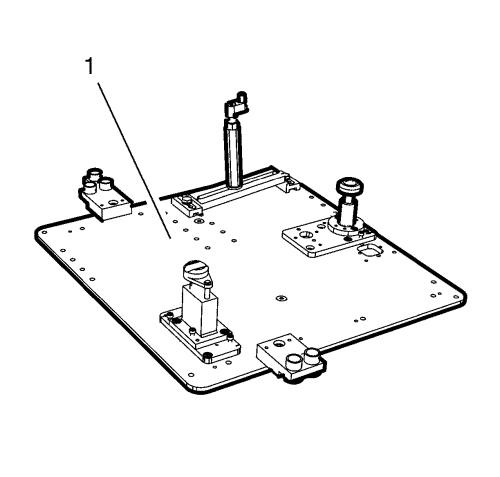
|
Note: Positioning
pins (1) of CH-49289 centring frame MUST be
extended in order to guide into underbody holes.
|
| 22. |
Move the frame (1) with the
engine transmission unit to the vehicle upward until the wiring
harness bracket can be fixed to the EPS unit. |
| 23. |
Install the wiring harness
bracket to the EPS unit. |
| 24. |
Tighten the 2 wiring harness
bracket bolts and tighten to 9 N·m (80 lb
in) . |
|
Note: Simplified
graphic. Engine/transmission unit is fixed with engine support tool
to suspension frame. Suspension frame is supported by centering
adapter and underframe.
|
| 25. |
Install the frame (4).
|
| 26. |
Install the frame
reinforcements (3). |
| 27. |
Install frame rear bolts (2).
Hand tighten ONLY. |
| 28. |
Install frame front bolts (3).
Hand tighten ONLY. |
| 29. |
Tighten the rear frame bolts
(2) and tighten to 160 N·m (118 lb ft)
. |
| 30. |
Tighten the front frame bolts
(1) and tighten to 160 N·m (118 lb ft)
. |
| 31. |
Lower the CH-49289
centring frame (1) with CH-904 base frame
and a jack. |
| 32. |
Remove the CH-49289
centring frame from the CH-904 base frame
. |
|
Note: The SPX
installation manual is supplied with the special tool and is also
available online from SPX directly. Go to
www.spxtools-shop.com.
|
| 33. |
Disassemble the
CH-49289 centering frame (1) according to the
details provided in the SPX installation manual. |
| 34. |
Install the 3 transmission
mount bolts (2) to the transmission mount (3) and the transmission
mount bracket (1) and tighten to 62 N·m (46 lb
ft) . |
| 35. |
Install the 3 engine mount
bolts (2) to the engine mount (1) and the engine mount bracket (3)
and tighten to 62 N·m (46 lb ft) .
|
| 36. |
Lower the CH-49290
support tool (1) with CH-904 base frame and
a jack. |
| 37. |
Remove the CH-49290
support tool from the CH-904 base frame
. |
|
Note: The SPX
installation manual is supplied with the special tool and is also
available online from SPX directly. Go to
www.spxtools-shop.com.
|
| 38. |
Disassemble the
CH-49290 support tool (1) according to the details
provided in the SPX installation manual. |
| 40. |
Connect the engine coolant fan
wiring harness plug (1) an clip to suspension frame (2).
|
| 41. |
Connect the EPS wiring harness
plug (3). |
| 42. |
Connect EPS main wiring
harness to EPS unit. |
| 43. |
Install the wheel speed sensor
wiring harness retainers from the frame. |
| 44. |
Connect the wheel speed sensor
on both sides. |
| 52. |
Install the A/C compressor and
condenser hose (2) and the seal ring (3) to air conditioning
evaporator hose. |
| 53. |
Install the A/C compressor and
condenser hose nut (1) to air conditioning evaporator hose and
tighten to 19 N·m (14 lb ft) . |
| 54. |
Install the lower condenser
hose (1) and the seal ring (2). |
| 55. |
Install the lower condenser
hose nut (3) and tighten to 19 N·m (14 lb
ft) . |
| 56. |
Remove the EN-6015
closure plugs . |
| 57. |
Connect fuel feed pipe (2) to
the fuel injector rail. |
| 58. |
Clip fuel feed pipe to
retainer clip (1). |
| 59. |
Connect fuel ventilation pipe
(4) to evaporative emission canister purge solenoid valve.
|
| 60. |
Clip fuel ventilation pipe to
retainer clip (3). |
| 61. |
Install fuel injector rail cap
(1). |
| 64. |
Fill the reservoir with
clutch/brake fluid up to the MAX level. |
| 65. |
Connect backup lamp switch
wiring harness electrical connector. |
| 66. |
Connect the booster vacuum
pipe (1) to the intake manifold. |
| 74. |
Install the ECM wiring harness
plug (1) to the lower part of the front compartment fuse
block. |
| 75. |
Connect the ECM wiring harness
plug (2) and clip it to retainer clip (3). |
| 76. |
Install the 3 wiring harnesses
(2). |
| 77. |
Install the 3 ground nuts (1)
and tighten to 9 N·m (80 lb in) .
|
|
Note: Ensure that the
3 wiring harness plugs (3), (5) and (6) fit clearly to the front
compartment fuse block.
|
| 78. |
Install the front compartment
fuse block (2) to the lower the lower part (4) and loosely install
the bolts (1). |
| 79. |
Clip in the front compartment
fuse block to the 4 retainer clips (2) and (3). |
| 80. |
Tighten the 3 front
compartment fuse block bolts (1) to 22 N·m (16 lb
ft) . |
| 81. |
Install the front compartment
fuse block cover (1). |
| 82. |
Install the windshield washer
solvent container filler tube (1). |
| 85. |
Check the oil level and fill
NEW engine oil up if necessary. |
|
