Engine Replacement (1.6L LDE - F17-5 MDG)
Special Tools
| • |
CH-49289
Centering Frame |
| • |
CH-49290
Engine Support Tool |
For equivalent regional tools, refer to
Special Tools .
Removal Procedure
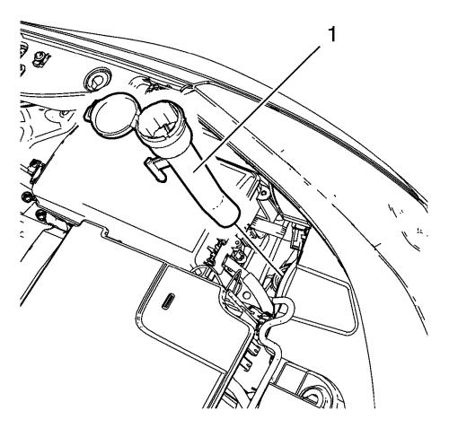
| 5. |
Remove the windshield washer
solvent container filler tube (1). |
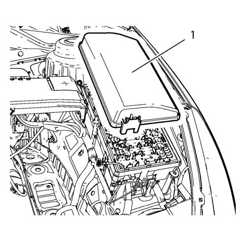
| 6. |
Remove the front compartment
fuse block cover (1). |
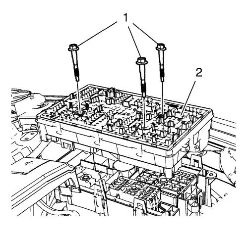
| 7. |
Remove the 3 front compartment
fuse block bolts (1). |
| 8. |
Remove the front compartment
fuse block (2). |
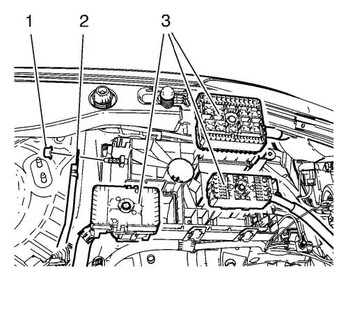
| 9. |
Unclip the 3 wiring harness
plugs (3). |
| 10. |
Disconnect the wiring harness
plug from the front compartment fuse block. |
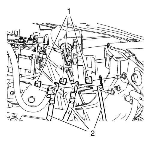
| 11. |
Remove the 3 ground nuts (1)
and put the 3 wiring harnesses (2) aside. |
| 12. |
Disconnect the 2 wiring
harness plugs (1, 2). |
| 17. |
Disconnect the coolant fill
sensor plug. |
| 18. |
Unclip the radiator surge
tank. |
| 19. |
Put the radiator surge tank
aside. |
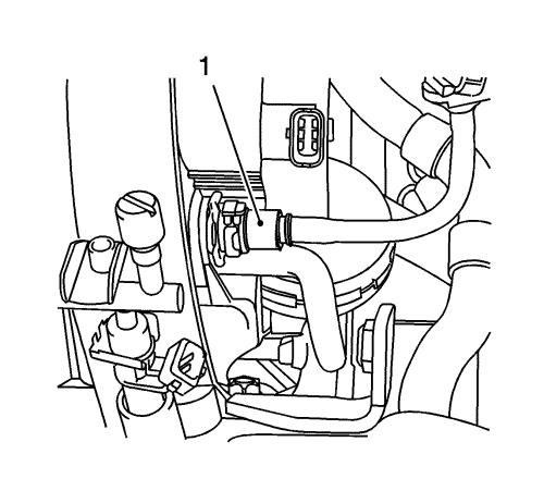
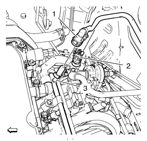
| 22. |
Disconnect the booster vacuum
pipe (1) from the intake manifold. |
| 23. |
Disconnect backup lamp switch
wiring harness electrical connector. |
| 24. |
Place collecting basin
underneath. |
| 26. |
Place collecting basin
underneath. |
|
Warning:
Gasoline or gasoline vapors are highly flammable.
A fire could occur if an ignition source is present. Never drain or
store gasoline or diesel fuel in an open container, due to the
possibility of fire or explosion. Have a dry chemical (Class B)
fire extinguisher nearby. |
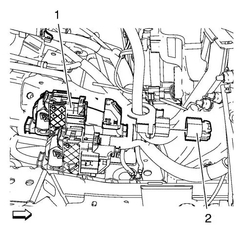
| 28. |
Clip the evaporative emission
canister purge pipe (3) out of the bracket (1). |
| 29. |
Remove the fuel tank vent pipe
(3) from the evaporative emission canister purge solenoid valve
(2). |
| 30. |
Close the vents with the
EN-6015 closure plugs . |
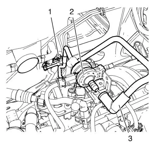
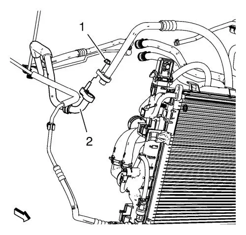
| 32. |
Release the fuel feed pipe (1)
from the multiport fuel injection fuel rail (3) and remove the fuel
feed pipe. |
| 33. |
Close the vents with the
EN-6015 closure plugs . |
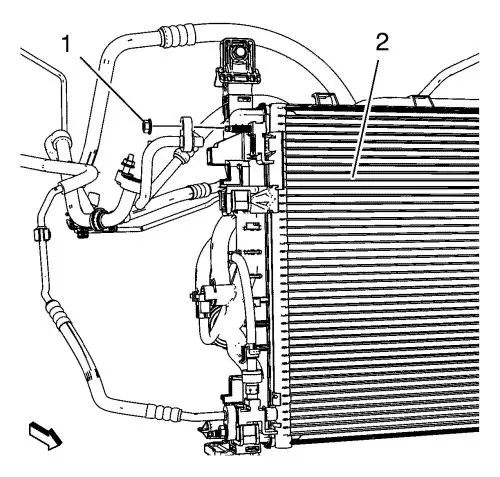
| 34. |
Remove A/C compressor and
condenser hose nut (1) from A/C condenser (2). |
| 35. |
Remove A/C compressor and
condenser hose nut (1) from refrigerant hose (2). |
| 36. |
Remove the air conditioning
evaporator hose assembly nut from the air conditioning
condenser. |
| 37. |
Unclip the radiator outlet
hose from the radiator. |
| 45. |
Disconnect the wheel speed
sensors on both sides. |
| 46. |
Remove the wheel speed sensor
wiring harness retainers from the frame. |
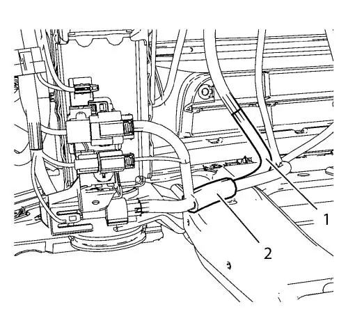
| 47. |
Unclip the 2 engine coolant
fan wiring harnesses (1, 2) from the frame. |
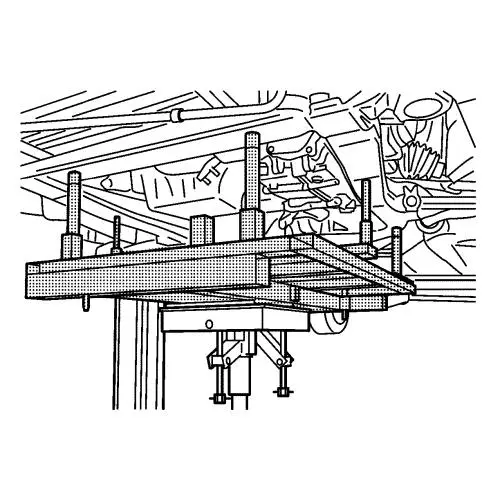
| 49. |
Install the CH-49290
engine support tool , for the assembly use attached
installation manual. |
| 52. |
Detach 3 wiring harness plugs
from the electronic power steering (EPS). |
| 53. |
Assemble the CH-49289
centring frame , for the assembly use attached installation
manual. |
| 54. |
Raise the CH-904
base frame and CH 49289 centring frame with
the hydraulic jack until it contacts the frame. |
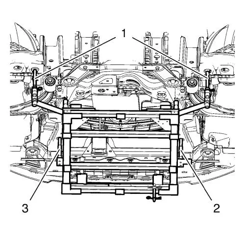
|
Note: Positioning
pins (2, 3) of CH-49289 centring frame MUST stick
into holes of drivetrain frame.
|
| 55. |
Check if wheel alignment is
required. |
| |
• |
Move out position pins (1) and
try to insert into underbody holes. |
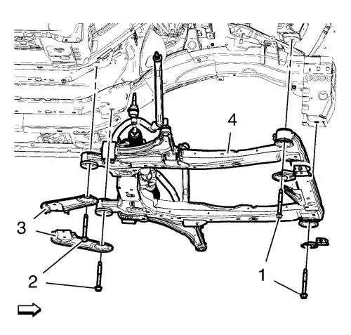
| 56. |
Remove the frame front bolts
(1). |
| 57. |
Remove the frame rear bolts
(2). |
| 58. |
Remove the frame
reinforcements (3). |
| 59. |
Lower suspension frame (4)
carefully with the engine transmission unit off the vehicle with
hydraulic jack about 7 cm. |
| 60. |
Remove the 2 wiring harness
starter bracket bolts. |
| 61. |
Remove the wiring harness
starter bracket from the electronic power steering (EPS).
|
| 62. |
Remove suspension frame
carefully with the engine transmission unit from the vehicle with
hydraulic jack. |
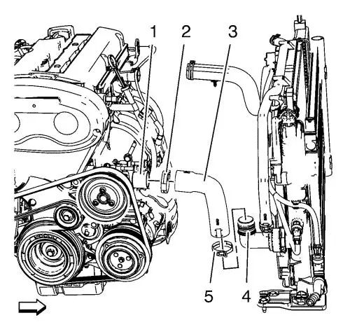
| 65. |
Loosen the radiator outlet
hose clamp (2). |
| 66. |
Remove the radiator outlet
hose (3) from the water pump (1). |
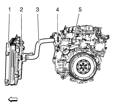
| 67. |
Loosen the radiator inlet hose
clamp (4). |
| 68. |
Remove the radiator inlet hose
(3) from the engine coolant thermostat (5). |
| 69. |
Remove the radiator
assembly. |
| 70. |
Install suitable cable at the
3 engine lift brackets. |
| 71. |
Install a suitable engine
lifting device to the cable. |
| 72. |
Extend the engine lifting
device until the steel cable are slightly tensioned. |
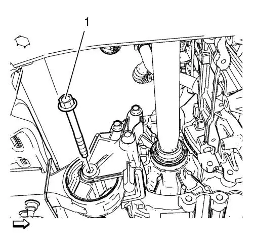
| 73. |
Remove the front transmission
mount through bolt (1). |
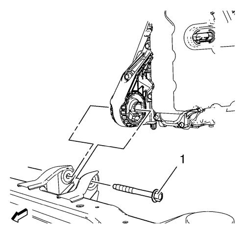
| 74. |
Remove the transmission
bracket mount to mount through bolt (1). |
| 75. |
Lower and remove the
frame. |
| 76. |
Put the engine transmission
unit down on a wooden pallet. |
|
Note: A second
technician is required.
|
| 78. |
Remove the last 2 transmission
bolts and the transmission. |
| 79. |
Install the engine to the
EN-49271 engine stand . |
| 80. |
Transfer parts as
needed. |
Installation Procedure
| 1. |
Remove the engine from the
EN-49271 engine stand . |
| 2. |
Put the engine down on a
wooden pallet. |
|
Note: A second
technician is required.
|
| 3. |
Install the transmission and 2
transmission bolts. |
| 4. |
Install the 6 transmission
bolts. |
| 6. |
Install suitable cable at the
3 engine lift brackets. Install a suitable engine lifting device to
the cable. Raise the engine transmission unit and extend the engine
lifting device until the steel cable are slightly tensioned.
|
| 7. |
Raise the CH-904
frame and CH-49289 centring frame with the
hydraulic jack until it contacts the frame. |
| 8. |
Place the engine transmission
unit into the front frame. |
| 9. |
Install the rear transmission
bracket mount to mount through bolt (1) and tighten to 100
N·m (74 lb ft) . |
| 10. |
Install the front transmission
mount through bolt (1) and tighten to 58 N·m (43 lb
ft) . |
| 11. |
Remove the cable from the 3
engine lift brackets. |
| 12. |
Install the radiator
assembly. |
| 13. |
Install the radiator inlet
hose (3) to the engine coolant thermostat (5). |
| 14. |
Install the radiator inlet
hose clamp (4). |
| 15. |
Install the radiator outlet
hose (3) to the water pump (1). |
| 16. |
Install the radiator outlet
hose clamp (2). |
|
Note: Positioning
pins (1) of CH-49289 centring frame MUST be
extended in order to guide into underbody holes.
|
| 19. |
Move the frame with the engine
transmission unit to the vehicle upwards, till wiring harness
starter can be fixed . |
| 20. |
Install the wiring harness
starter bracket to electronic power steering (EPS). |
| 21. |
Install and tighten the 2
wiring harness starter bracket bolts. |
| 22. |
Install the frame (4).
|
| 23. |
Install the frame
reinforcements (3). |
| 24. |
Install frame rear bolts (2).
Handtighten ONLY. |
| 25. |
Install frame front bolts (1).
Handtighten ONLY. |
| 26. |
Tighten the frame rear bolts
(2) and tighten to 160 N·m (118 lb ft)
. |
| 27. |
Tighten the frame front bolts
(1) and tighten to 160 N·m (118 lb ft)
. |
| 28. |
Lower the CH-49289
centring frame with the hydraulic jack until it is
removable. |
| 29. |
Disassemble the
CH-49289 centring frame , for the assembly use
attached installation manual. |
| 32. |
Remove the CH-49290
engine support tool , for the disassembly use attached
installation manual. |
| 33. |
Connect the 3 wiring harness
connectors to the electronic power steering (EPS). |
| 35. |
Clip the 2 engine coolant fan
wiring harnesses (1, 2) into the frame. |
| 36. |
Install the wheel speed sensor
wiring harness retainers from the frame. |
| 37. |
Connect the wheel speed sensor
on both sides. |
| 46. |
Clip the Radiator outlet hose
into the radiator. |
| 47. |
Install the air conditioning
evaporator hose assembly nut to the air conditioning condenser and
tighten to 19 N·m (14 lb ft) . |
| 48. |
Install the A/C compressor and
condenser hose nut (1) to the A/C condenser (2). Tighten the nut to
19 N·m (14 lb ft) . |
| 49. |
Install the A/C compressor and
condenser hose nut (1) to the refrigerant hose (2). Tighten the nut
to 19 N·m (14 lb ft) . |
| 50. |
Remove the EN-6015
closure plugs . |
| 51. |
Connect the fuel filler pipe
to the multiport fuel injection fuel rail. |
| 52. |
Remove the EN-6015
closure plugs . |
| 53. |
Connect the fuel tank vent
pipe to the evaporative emission vent valve. |
| 56. |
Fill the reservoir with
clutch/brake fluid up to the MAX level. |
| 57. |
Connect backup lamp switch
wiring harness electrical connector. |
| 58. |
Connect the booster vacuum
pipe (1) to the intake manifold. |
| 61. |
Connect the coolant fill
sensor plug. |
| 62. |
Clip in the radiator surge
tank. |
| 67. |
Connect the 2 wiring harness
plugs (1, 2). |
| 68. |
Install the 3 wiring harnesses
(2). |
| 69. |
Install the 3 ground nuts (1)
and tighten to 9 N·m(80 lb in) .
|
| 70. |
Clip in the 3 wiring harness
plugs (3). |
| 71. |
Connect the wiring harness
plug to the front compartment fuse block. |
| 72. |
Install the front compartment
fuse block (2). |
| 73. |
Install the 3 front
compartment fuse block bolts (1) and tighten to 22
N·m (16 lb ft) . |
| 74. |
Install the front compartment
fuse block cover (1). |
| 75. |
Install the windshield washer
solvent container filler tube (1). |
| 78. |
Check the oil level and fill
NEW engine oil up if necessary. |
|
