Intake Manifold Replacement (1.7L Diesel LPL, LPV and LUB)
Removal Procedure
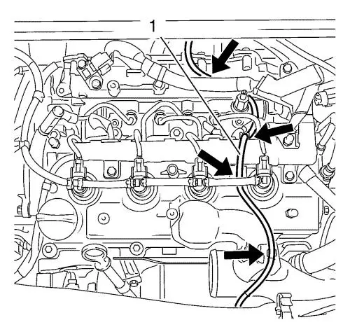
| 5. |
Detach the vacuum hose (1)
from the exhaust gas recirculation cooler. |
| 6. |
Unclip the vacuum hose from
the 4 retainer clips see arrows and set the vacuum hose
aside. |
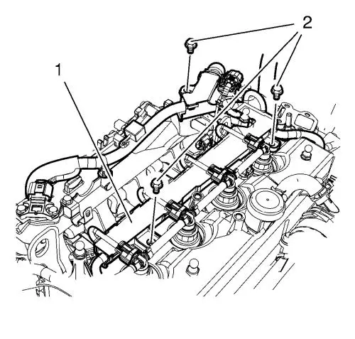
| 7. |
Remove the 3 wiring harness
bolts (2) from the wiring harness (1). |
| 8. |
Disconnect the following
engine wiring harness plugs: |
| |
• |
Coolant temperature sensor
wiring harness plug |
| |
• |
Throttle body wiring harness
plug |
| |
• |
4 Injector wiring harness
plugs |
| |
• |
4 glow plug wiring harness
plugs |
| |
• |
Camshaft sensor wiring harness
plug |
| |
• |
Air intake temperature sensor
wiring harness plug |
| |
• |
2 solenoid valve wiring
harness plugs |
| |
• |
Engine control module wiring
harness plug |
| |
• |
Glow plug controller wiring
harness plug |
| |
• |
Wiring harness connection
plug |
| 9. |
Unclip the wiring harness from
the 6 retainer clips and set the wiring harness (1) aside.
|
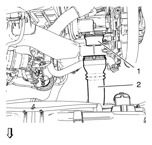
| 10. |
Disconnect the charge air
cooler outlet air hose (2) from the throttle body (1). |
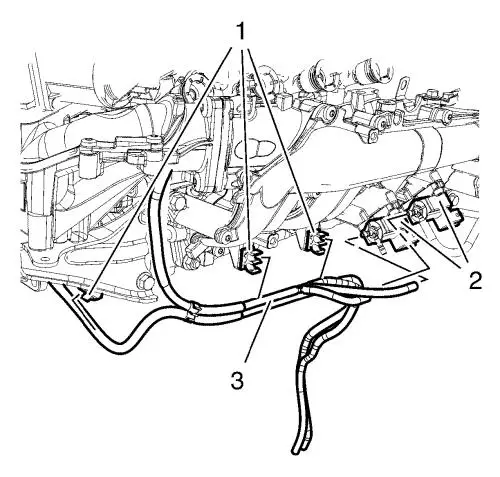
| 12. |
Detach the 2 vacuum hoses (3)
from the 2 vacuum regulator solenoid valves (2). |
| 13. |
Unclip the vacuum hoses from 5
clips (1). |
| 14. |
Remove the intake manifold
assembly with the intake pipe and the throttle body. Refer to
Intake Manifold Removal . |
Installation Procedure
| 4. |
Attach the 2 vacuum hoses (3)
to 2 vacuum regulator solenoid valves (2). |
| 5. |
Clip in the vacuum hoses to 5
clips (1). |
| 7. |
Connect the charge air cooler
outlet air hose (2) to the throttle body (1). |
| 8. |
Connect the following engine
wiring harness plugs: |
| |
• |
Coolant temperature sensor
wiring harness plug |
| |
• |
Throttle body wiring harness
plug |
| |
• |
4 Injector wiring harness
plugs |
| |
• |
4 glow plug wiring harness
plugs |
| |
• |
Camshaft sensor wiring harness
plug |
| |
• |
Air intake temperature sensor
wiring harness plug |
| |
• |
2 solenoid valve wiring
harness plugs |
| |
• |
Engine control module wiring
harness plug |
| |
• |
Glow plug controller wiring
harness plug |
| |
• |
Wiring harness connection
plug |
| 9. |
Clip in the wiring harness (1)
to the 6 retainer clips. |
| 10. |
Install the 3 wiring harness
bolts (2) to the wiring harness (1) and tighten to 9
N·m (80 lb in) . |
| 11. |
Clip in the vacuum hose to the
4 retainer clips see arrows. |
| 12. |
Attach the vacuum hose (1) to
the exhaust gas recirculation cooler. |
|
