Cylinder Head Replacement
Special Tools
| • |
CH-49290
Mounting Engine / Transmission |
| • |
EN-45059
Torque Angle Sensor Kit |
For equivalent regional tools, refer to
Special Tools .
Removal Procedure
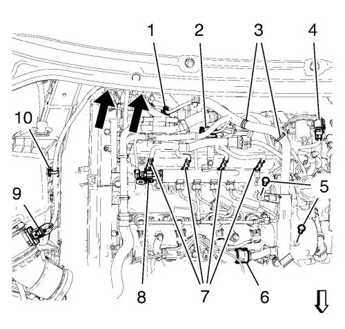
| 4. |
Remove the 2 conduit bolts
(5). |
| 5. |
Disconnect following
connections: |
| |
• |
from the 4 glow plugs
(7) |
| |
• |
from manifold pressure sensor
(2) |
| |
• |
from fuel injection pump
(1) |
| |
• |
from air mass sensor
(9) |
| 6. |
Remove the wiring harness
retainer (10) from the air filter assembly and from the bracket
(see arrows in picture). |
| 7. |
Hang the wiring harness
aside. |
| 16. |
Install the CH-49290
mounting , for the assembly use attached installation
manual. |
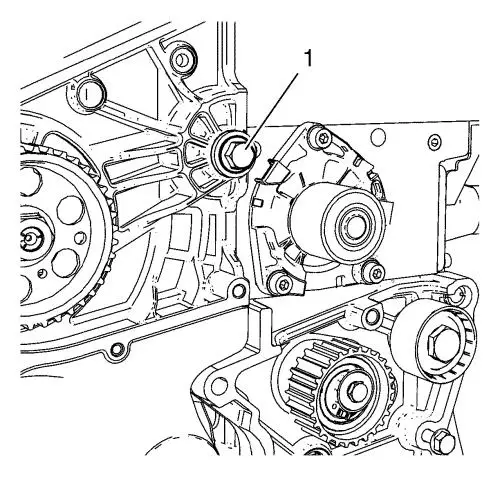
| 18. |
Remove the fuel injection pump
bracket bolt (1). |
| 19. |
Remove the upper positive
crankcase ventilation oil separator bolt. |
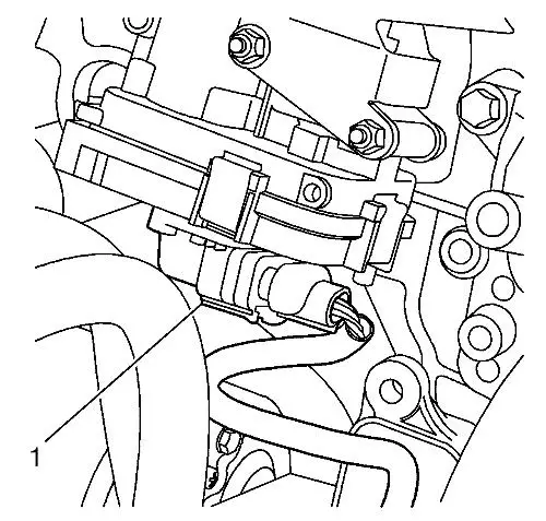
| 22. |
Disconnect the wiring harness
plug (1) from the manifold actuator. |
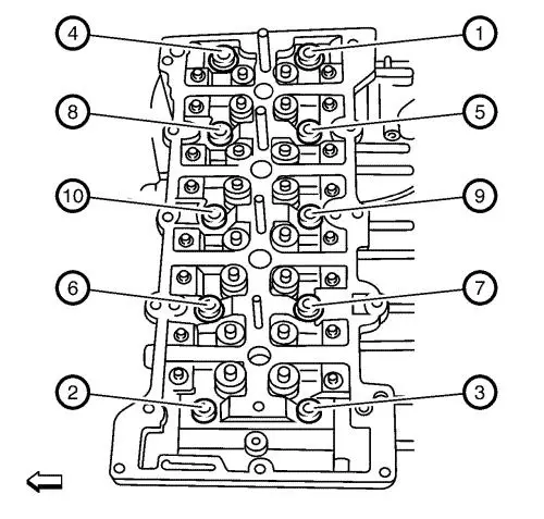
| 24. |
Loosen the 10 cylinder head
bolts in the sequence as shown. Use the following procedure:
|
| |
24.1 |
Loosen the cylinder head bolts
90° . |
| |
24.2 |
Loosen the cylinder head bolts
180° . |
|
Note: Do not damage
the guide sleeves (4) and (5).
|
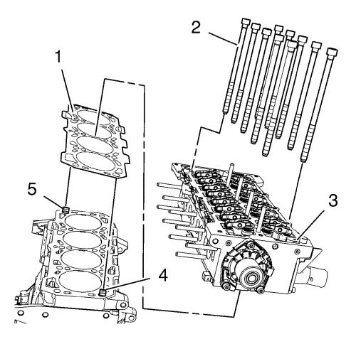
| 25. |
Remove and DISCARD the 10
cylinder head bolts (2). |
| 26. |
Remove the cylinder head
(3). |
| 27. |
Remove the cylinder head
gasket (1). |
| 28. |
Remove the assembly parts from
the cylinder head: |
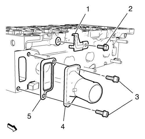
| 29. |
Remove the bracket bolt (2)
and the bracket (1). |
| 30. |
Remove the water outlet bolts
(3). |
| 31. |
Remove the water outlet (4) in
conjunction with the water outlet gasket (5). |
Installation Procedure
|
Caution: Clean all dirt, debris, and coolant from the engine block
cylinder head bolt holes. Failure to remove all foreign material
may result in damaged threads, improperly tightened fasteners or
damage to components. |
|
Note:
| • |
Do not use the
cylinder head bolts again. Install NEW cylinder head bolts during
assembly. |
| • |
Do not use any
type of sealant on the cylinder head gasket, unless
specified. |
| • |
The cylinder head
gaskets must be installed in the proper direction and
position. |
|
| 1. |
Clean the sealing surfaces and
remove all remains of dirt and old gasket material from thread
bores, water galleries and oil galleries. |
| 2. |
Check the flatness of the
cylinder head and cylinder block with a steel rule and inspect for
damage to the sealing surfaces. |
| 3. |
Install the water outlet (4)
in conjunction with a NEW water outlet gasket (5). |
| 4. |
Install the water outlet bolts
(3) and tighten to 9 N·m (80 lb in)
. |
| 5. |
Install the bracket
(1). |
| 6. |
Install the bracket bolt (2)
and tighten to 9 N·m (80 lb in) .
|
| 7. |
Install the assembly parts
from the cylinder head: |

|
Note: Always take the
same thickness like the old gasket.
|
| 8. |
Check the right thickness of
the NEW cylinder head gasket (1). It is marked as shown in
picture: |
| |
• |
without a hole: 0.95
mm (0.0374 in) |
| |
• |
with one hole: 1.05 mm
(0.0413 in) |
| |
• |
with two holes: 1.15
mm (0.0452 in) |
|
Note: Do not damage
the guide sleeves (4) and (5) and do not confuse the engine block
guide sleeves with the camshaft guide sleeves.
|
| 9. |
Install a NEW cylinder head
gasket (1). The marking "Top" should point to the cylinder
head. |
| 10. |
Install the cylinder head
(3). |
| 11. |
Loosely install 10 NEW
cylinder head bolts (2). |
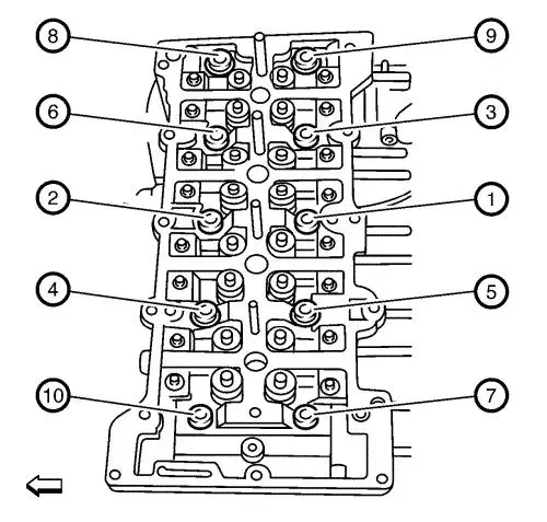
| 12. |
Tighten the 10 NEW cylinder
head bolts in following order: |
|
Note: The following
tightening order applies to ribe cylinder head bolts.
|
| |
12.1 |
First pass in sequence to
20 N·m (15 lb ft) . |
| |
12.2 |
Second pass in sequence to
65 N·m (48 lb ft) . |
| |
12.3 |
Third pass in sequence to an
additional 90° using the EN 45059
angle sensor . |
| |
12.4 |
Fourth pass in sequence to an
additional 90° using the EN 45059
angle sensor . |
| |
12.5 |
Fifth pass in sequence to an
additional 90° using the EN 45059
angle sensor . |
|
Note: The following
tightening order applies to torx T60 cylinder head bolts.
|
| |
12.1 |
First pass in sequence to
20 N·m (15 lb ft) . |
| |
12.2 |
Second pass in sequence to
65 N·m (48 lb ft) . |
| |
12.3 |
Third pass in sequence to an
additional 90° using the EN 45059
angle sensor . |
| |
12.4 |
Fourth pass in sequence to an
additional 90° using the EN 45059
angle sensor . |
| |
12.5 |
Fifth pass in sequence to an
additional 90° using the EN 45059
angle sensor . |
| |
12.6 |
Sixth pass in sequence to an
additional 90° using the EN 45059
angle sensor . |
| 15. |
Connect the wiring harness
plug (1) from the manifold actuator. |
| 17. |
Install the upper positive
crankcase ventilation oil separator bolt and tighten to 9
N·m (80 lb in) . |
| 18. |
Install the fuel injection
pump bracket bolt (1) and tighten to 25 N·m (18 lb
ft) . |
| 20. |
Remove the CH-49290
mounting . |
| 29. |
Install the wiring
harness. |
| 30. |
Connect the following
connections: |
| |
• |
to the 4 glow plugs (7)
|
| |
• |
to manifold pressure sensor
(2) |
| |
• |
to fuel injection pump
(1) |
| 31. |
Install the 2 conduit bolts
(5). |
| 32. |
Install the wiring harness
retainer (10) to the air filter assembly and to the bracket (see
arrows in picture). |
|
