|
Retaining Frame – Brake Calliper of Rear
Wheel Brake, Remove and Install
 Remove Remove
| 1. |
Detach rear wheel
| • |
Mark position in relation to centre of wheel
|
|
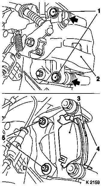
| 2. |
Remove fastening bolts of brake calliper guide pins (1)
| • |
During this, counterhold on hexagonal section of the guide pin
(arrows)
|
| • |
Remove brake calliper (2) from retaining frame and hang up
|
|
| 3. |
Remove brake linings (3) and sliding plates (4) from retaining
frame
| • |
Detach both fastening bolts (5) from retaining frame for brake
calliper on wheel bearing unit
|
| • |
Remove retaining frame.
|
|
|
|
| 4. |
Clean threads of fixing bolts for retaining frame and guide
pins.
|
 Install
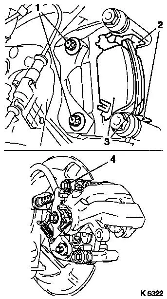
| 5. |
Attach retaining frame to wheel bearing unit
| • |
Coat fastening bolts for brake calliper retaining frame (1)
with locking compound
|
| • |
Tighten fastening bolts, tightening torque 65 Nm
|
|
| 6. |
Insert sliding plates (2) and brake linings (3) in retaining
frame
| • |
Coat retaining frame and sliding frames in the area of the
contact surfaces of the brake linings with special grease 
|
| • |
Insert the brake lining with the wear indicator on the inside
of the retaining frame (piston side of the brake calliper).
|
| • |
Coat thread of fastening bolts of the guide pins with bolt
locking compound
|
| • |
Unhitch brake calliper and fit to retaining frame guide pin
using upper fastening bolts (4) - tightening torque 45 Nm
| – |
Counterhold at hex of upper guide pin (arrows).
|
|
|
|
|
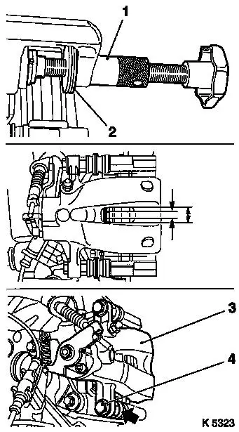
| 7. |
Press piston of brake calliper back into the housing with KM-6007 (1) and KM-6007-10 (2) back into the housing
Note: In doing so
ensure that the piston is located with a recess aligned with the
inspection aperture of the brake calliper (arrows see
illustration).
|
| 8. |
Fold brake calliper downwards (3).
| • |
Attach with fastening bolt for lower guide pin (4) - tightening
torque 27 Nm
| – |
Counterhold hexagonal section of lower guide pin (arrow).
|
|
|
|
|
| 9. |
Fit rear wheel - tightening torque 110
Nm
|
|
