|
J461900 Camshaft Housing, Replace (Y 17 DTL,
without AC, LHD)
Note: KM-6394 must be used from model year 04 instead of
KM-6169-1 .
1. Open bonnet
Caution!
On vehicles from model year 04 with ESP - the steering angle
sensor loses its basic adjustment each time the battery is
disconnected. It must be recalibrated.
2. Disconnect battery
3. Detach front right wheel
4. Raise vehicle
5. Remove front right wheel
6. Raise vehicle
|
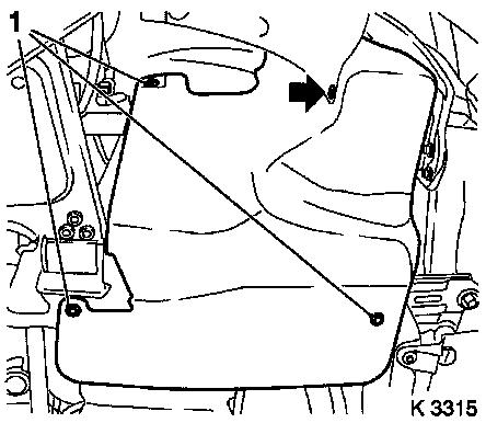
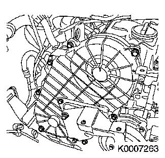
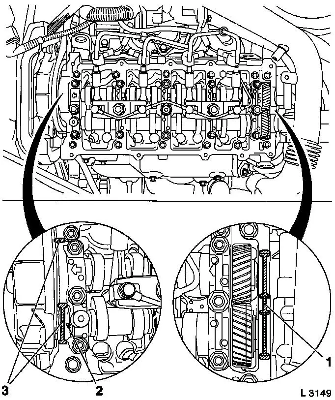
7. Remove ribbed V-belt cover
- Remove 3 bolts (1)
- Remove clip (arrow).
|
|
8. Loosen air intake pipe.
|
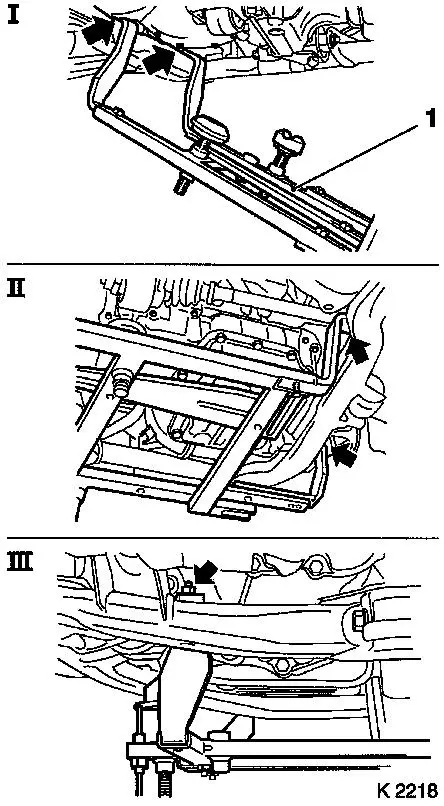
9. Attach KM-6169 (1)
- Place left of KM-6169 onto front axle body (arrows, illus.
I)
- Note! Guide pin must be seated in bore in front axle body
- Attach both right holders on the front axle body (arrows,
Illus. II).
- Note! Guide pin must be seated in bore in front axle body
(arrow, Illus. III)
- Tighten bolts
|
|
|
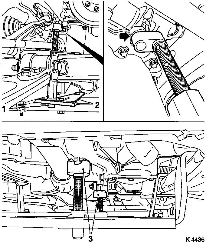
10. Install support
- To KM-6169
- Adjust bracket (2) for support
- Screw on nut (1)
|
|
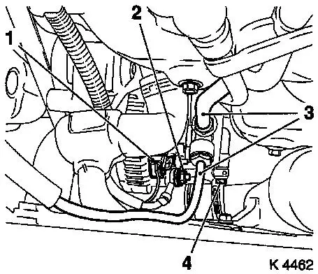
11. Adjust supports
- Transmission side
- Note! Turn spindles until the mounts (3) are positioned at the
guide journals free of play
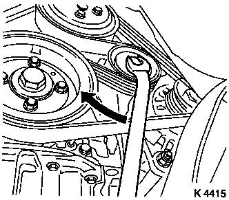
- Engine timing side
- Insert journal of the support in the bore of the cylinder block
without play (arrow)
- Tighten nuts (1)
|
12. Lower vehicle
|
|
|
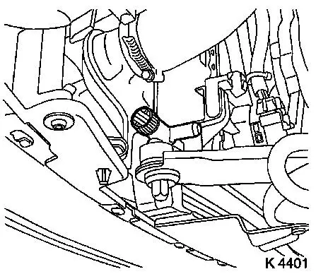
13. Drain coolant
- Place collecting basin underneath.
- Remove drain bolt
|
|
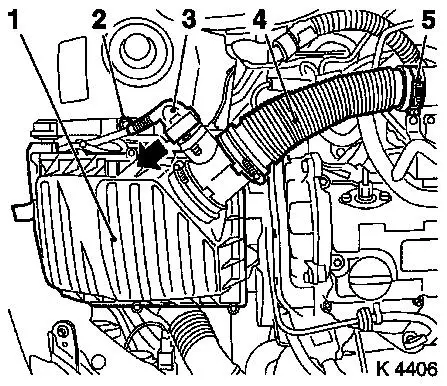
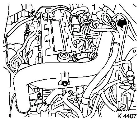
14. Remove air cleaner housing (1)
- Remove wiring harness plug for hot film mass air flow meter
(3)
- Release in direction of arrow
- Remove air intake hose (4)
- Remove bolt (2)
|
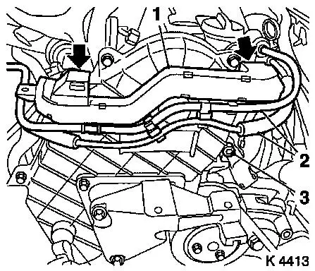
15. Detach air intake pipe
- Remove 3 bolts
- Remove vent hose (1)
- Detach air intake pipe from turbocharger
- Unclip wiring harness
|
|
|
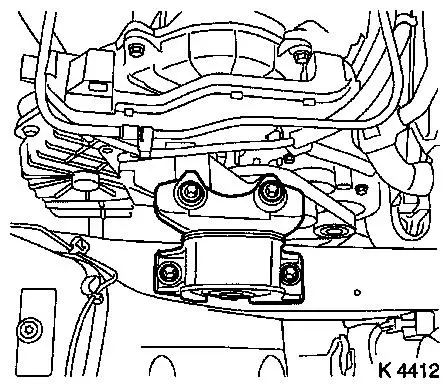
16. Remove right engine damping
block
|
|
17. Detach alternator wiring
harness
- Disconnect wiring harness plug (1)
- Unscrew nut (2)
|
18. Detach vacuum hoses for vacuum pump
(3)
- Brake servo
- Exhaust gas recirculation solenoid valve
|
|
|
19. Remove wiring trough
- Unclip vacuum lines (2)
- Unclip wiring trough (1)
- Remove bolt (3)
|
|
|
20. Release upper toothed belt
cover
- Remove 8 bolts
- Note! Note dissimilar bolt lengths
|
|
|
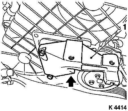
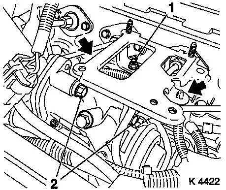
21. Detach right engine bracket (1)
- Remove 3 bolts
- Remove right engine bracket, right engine bracket adapter,
upper part of toothed belt cover
|
|
22. Raise vehicle
|
23. Loosen coolant pump ribbed V-belt
pulley (1)
|
|
|
24. Detach ribbed V-belt
- Tension ribbed V-belt tensioner in direction of arrow
- Note! Mark running direction
|
|
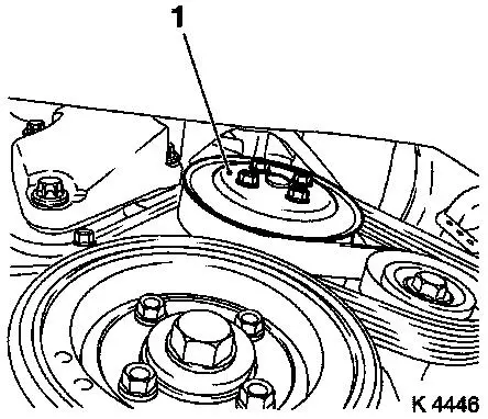
25. Detach coolant pump ribbed V-belt
pulley
|
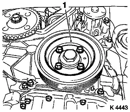
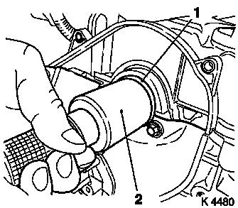
26. Remove torsional vibration damper
(1)
|
|
|
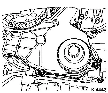
27. Remove lower toothed belt cover
|
|
|
28. Set 1st cylinder to TDC
- Turn crankshaft evenly until TDC-fixing bolts can be
inserted
- Camshaft gear (M6) (1)
- Injection pump gear (M8) (2)
- Note! The mark on toothed belt drive gear must align with lug
on oil pump cover (arrows)
|
|
29. Lower vehicle
|
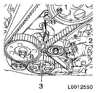
30. For toothed belt tension roller
with leaf spring:
- loosen toothed belt tensioner
- Screw in bolt (M10) in lower bore (3) of toothed belt
tensioner
- Loosen bolt (2)
- Remove tension spring (1)
|
|
|
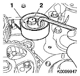
For toothed belt tension roller with
spiral spring:
- Loosen toothed belt tension roller (1)
- Rotate toothed belt tension roller anticlockwise approx.
90°
- Tighten bolt (2)
|
|
31. Remove toothed belt
- Note! Mark running direction
|
32. Detach camshaft pulley
- Unscrew TDC-fixing bolt (2)
- Remove bolt (1)
- Counterhold using KM-6156 and KM-956-1
|
|
|
32. Loosen rear toothed belt cover
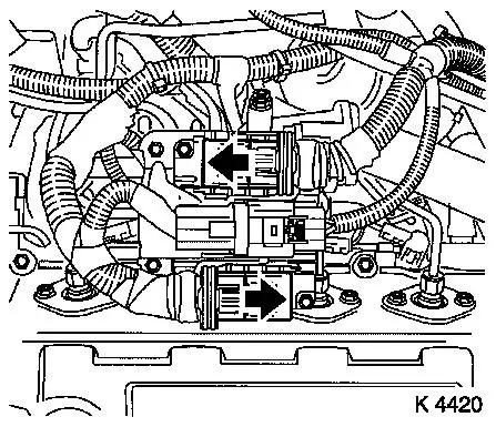
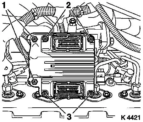
34. Detach engine control unit wiring harness plug
- 3 off
- Release 2 wiring harness plugs in direction of arrow
|
|
|
35. Remove engine control unit
- Remove wiring harness plug bracket
- Unscrew 2 bolts (2), 2 nuts (3)
|
|
|
36. Remove engine control unit
bracket
- Unscrew 2 bolts (2), nut (1)
- Unclip wiring harness (arrows)
|
|
37. Remove rear right engine transport
shackle
38. Release left rear engine transport shackle
39. Detach oil leak line
40. Detach injection lines
|
41. Detach injection nozzle outer
seals
|
|
42. Detach oil dipstick guide tube
bracket
|
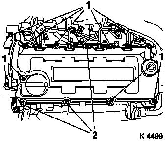
43. Remove camshaft housing cover
- Unscrew 7 bolts (1), 3 studs (2)
|
|
44. Remove camshaft housing cover
- Note! 2. mechanic
- Carefully push injection line to rear
45. Detach inner oil leak line
- Remove 5 banjo bolts
- Note! Note sealing rings
|
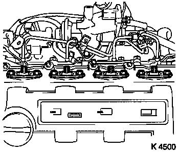
46. Remove injector nozzles
Caution!
Ensure that upon removal of injector
nozzles heat protection sleeves remain in their position on the
cylinder head. Otherwise, heat protection sleeves must be removed
completely and installed again using new sealing rings. This is the
only way to ensure that no coolant can reach the combustion
chamber, which would inevitably cause engine damage. Replace heat
protection sleeves – see operation "Replace heat protection
sleeves" in document "Check and measure cylinder head".
- Remove injection nozzle bracket (1)
- Remove injector nozzles
|
|
|
47. Lock exhaust camshaft equaliser
gear
- Insert KM-955-2 (1)
- Note! Insert in exhaust camshaft gear and exhaust camshaft
equaliser gear up to camshaft bearing cap stop. Exhaust camshaft
gear and exhaust camshaft equaliser gear must be locked in place
with rotation impossible
|
|
|
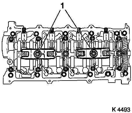
48. Remove camshaft bearing caps
- 5 off
- Remove 15 nuts
- Note! Note identification on camshaft bearing caps. The
camshafts must be uniformly released from the bearing seats. Loosen
nuts (180° – 360°)
|
|
|
49. Remove camshafts
- Remove intake camshaft seal ring
|
|
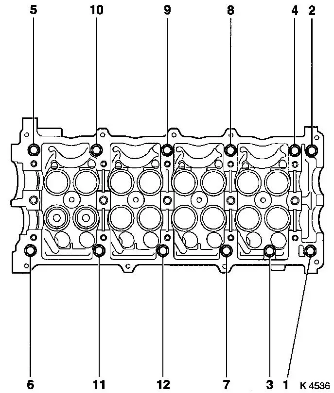
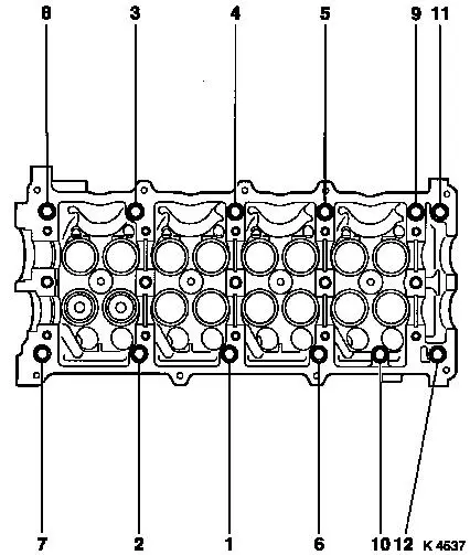
50. Remove camshaft housing cover
- Loosen bolts (180°)
- Caution! Observe sequence (1 - 12)
- Remove 12 bolts
- Remove gasket.
|
51. Detach outer oil leak line
- Unscrew banjo bolt
- Remove bolt
|
|
52. Attach outer oil leak line
- Tighten banjo bolt (14.7 Nm / 10.8 lbf. ft.)
- Tighten bolt (14.7 Nm / 10.8 lbf. ft.)
53. Clean sealing surfaces
- Cylinder head, camshaft housing, camshaft housing cover,
exhaust recirculation valve
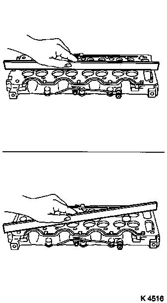
54. Check for plane surface
- camshaft housing
- With straightedge
|
55. Install camshaft housing
- Replace gasket
- Tighten bolts (21.6 Nm / 15.9 lbf. ft.)
- Caution! Observe sequence (1 - 12)
|
|
|
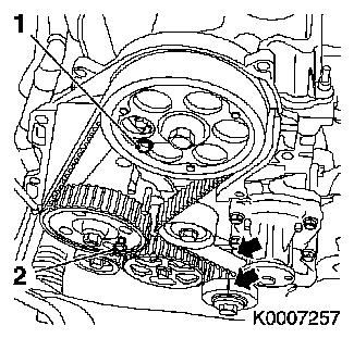
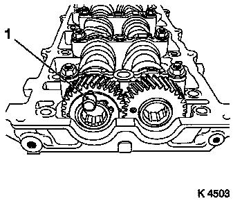
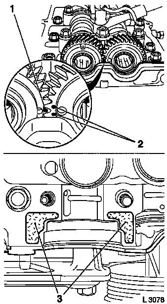
56. Insert camshafts
- Caution! Mark on exhaust camshaft gear (1) must be positioned
between both intake camshaft gear marks (2). The marks must be in
one plane with the top edge of the camshaft housing
|
|
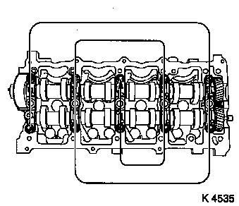
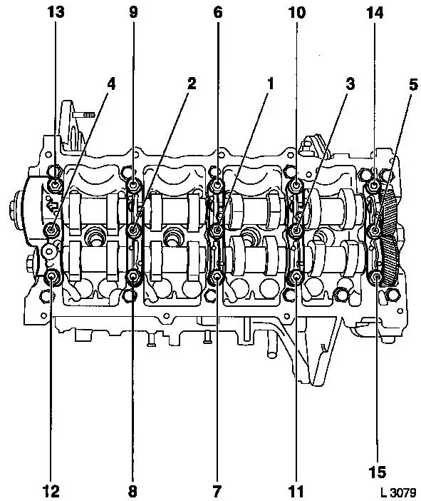
57. Attach camshaft bearing caps
- Note! Apply surface sealant (green) to sealing surfaces of 1st
camshaft bearing cap (3)
- 5 off
- Screw in nuts
|
58. Attach camshaft bearing caps
- Tighten nuts M8 (21.6 Nm/15.9 lbf. ft.), M10 (43.1 Nm/31.8 lbf.
ft.)
- Caution! Observe sequence (1 - 15)
- Remove KM-955-2
|
|
|
59. Install intake camshaft seal ring
(1)
- Coat seal lips with grease
- Slide onto camshaft
- Drive in until flush using KM-656 (2)
|
|
60. Attach rear toothed belt cover
- Tighten bolts (9.8 Nm / 7.2 lbf. ft.)
61. Attach camshaft gear
- Lock with KM-6156 and KM-956-1
- Tighten bolt (63.7 Nm / 47.0 lbf. ft.)
- Install TDC-fixing bolt
|
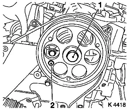
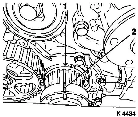
62. Set cylinder 1 to TDC
- Mark on toothed belt drive gear (2) must align with casting lug
at oil pump cover (1)
|
|
63. Install toothed belt
Note: Toothed belt
must be taut from toothed belt drive gear via oil pump drive gear
and injection pump drive gear
- For toothed belt tension roller with leaf spring:
- Unscrew TDC-fixing bolt
- Rotate crankshaft 60° against direction of engine
rotation
- Tighten bolt of toothed belt tension roller
- For toothed belt tension roller with spiral spring 49 Nm
- For toothed belt tension roller with leaf spring 38.2 Nm
- For toothed belt tension roller with leaf spring: unscrew bolt
(M10) from lower bore of toothed belt tensioner
65. Timing, Check
- Turn crankshaft approx. 780° in direction of engine
rotation
- At toothed belt drive gear bolt
- Mark on toothed belt drive gear (2) must align with casting lug
at oil pump cover (1)
- Screw in TDC-fixing bolts (arrows)
- Install torsional vibration damper
- Note! Mark on torsional vibration damper (3) must align with
pin (4) on oil pump cover If the TDC fixing bolts cannot be
inserted, the basic adjustment must be repeated
66. Unscrew TDC-fixing bolts
67. Remove torsional vibration
damper
|
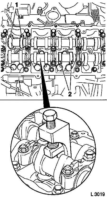
68. Rotate crankshaft
- Turn crankshaft until cam pairs (1) and (2) point upwards
|
|
69. Check valve clearance
- Using feeler gauge
- Test values: Intake valves/Exhaust valves (0.35 – 0.45
mm)
- Note! The valve clearances are checked on a cold engine –
room temperature
70. Adjust valve clearance
- Turn cup tappet until tappet groove points outwards
- Press down cup tappets using KM-6090
- Note! Note different tool versions for intake and exhaust
valves
- Mark – IN = Intake side
- Mark – EX = Exhaust side
- Caution! Ensure that valves do not interfere with piston
head
- Remove adjustment shim
|
Example for determination of shim
thickness
|
1.
|
Thickness of installed shim
|
|
3.15 mm
|
|
2.
|
Measurement between cam and cup tappets
|
+
|
0.45 mm
|
|
|
|
=
|
3.60 mm
|
|
3.
|
Nominal valve play
|
-
|
0.40 mm
|
|
4.
|
Thickness of new shim
|
=
|
3.20 mm
|
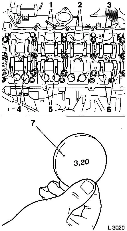
71. Insert adjustment shim
- Coat new shim (7) with engine oil and insert in cup tappet with
identification mark facing downwards.
72. Rotate crankshaft
- In direction of engine rotation by 180°
- Check and adjust valve pair (6) and (2)
- In direction of engine rotation by 180°
- Check and adjust valve pair (5) and (3)
- In direction of engine rotation by 180°
- Check and adjust valve pair (4) and (1)
- Note! Valve clearances must be checked again for all adjusted
valves
|
|
73. Attach lower part of toothed belt
cover
- Tighten bolts (9.8 Nm / 7.2 lbf. ft.)
74. Attach right engine bracket
- Insert lower bolt
- Into right engine bracket and right engine bracket adapter
- Insert right engine bracket, right engine bracket adapter,
upper part of toothed belt cover
- Install 2 upper bolts
- Tighten 3 bolts (40 Nm / 29.5 lbf. ft.)
75. Fasten upper part of toothed belt
cover
- Tighten bolts (9.8 Nm / 7.2 lbf. ft.)
- Note! Note dissimilar bolt lengths
76. Attach coolant pump ribbed V-belt
pulley
77. Raise vehicle
78. Install torsional vibration
damper
- Tighten bolts (19.6 Nm / 14.5 lbf. ft.)
79. Install ribbed V-belt
- Note! Observe running direction and installation position
80. Release ribbed V-belt tensioner
81. Fasten coolant pump ribbed V-belt
pulley
- Tighten bolts (9.8 Nm / 7.2 lbf. ft.)
82. Lower vehicle
83. Install right engine damping
block
- To side member
- Tighten bolts (40 Nm / 29.5 lbf. ft.)
- On engine bracket
- Tighten bolts (60 Nm/44 lbf. ft + 30° + 15°.)
84. Install injector nozzles
- Renew seal rings
- Renew copper sealing washers
- Insert injection nozzles in cylinder head.
- Install injector nozzle bracket (22.1 Nm/16.3 lbf. ft.)
85. Attach new inner oil leak line
- Renew seal rings
- Tighten banjo bolt (14.7 Nm/10.8 lbf. ft.)
|
86. Attach camshaft housing cover
- Replace gasket
- Apply adhesive sealant compound (white)
- Caution! Oil return bore (2) must not be covered with adhesive
sealing compound or by the camshaft housing cover gasket
|
|
87. Install camshaft housing cover
- Note! 2. mechanic
- Carefully push injection line to rear
88. Tighten camshaft housing cover
- Tighten bolts, studs (9.8 Nm/7.2 lbf. ft.)
89. Install oil dipstick guide tube
bracket
90. Attach injection nozzle outer
seals
- Replace seals
- Tighten bolts
91. Install injection lines
- Tighten union nuts (22.5 Nm/16.6 lbf. ft.)
92. Fasten rear left engine transport
shackle
- Tighten bolts (20 Nm / 15 lbf. ft.)
93. Install right rear engine transport
shackle
- Tighten bolt (20 Nm / 15 lbf. ft.)
94. Attach oil leak hose
95. Attach wiring trough
- Clip-in wiring trough
- Clip in vacuum lines
- Tighten bolt
96. Install alternator wiring
harness
- Connect wiring harness plug.
- Tighten nuts
97. Attach vacuum pump vacuum lines
- Route lines and clip in
- Tighten union nut (18 Nm/13.3 lbf. ft.)
98. Install engine control unit
bracket
- Tighten bolts (24.5 Nm/18.1 lbf. ft.)
- Tighten nut (9.8 Nm/7.2 lbf. ft.)
- Attach wiring harness
99. Install engine control unit
- Tighten bolts, nuts (5.9 Nm/4.4 lbf. ft.)
- Install wiring harness plug bracket
100. Install air intake pipe
- Tighten bolts
- Tighten clamp (3.5 Nm / 2.6 lbf. ft.)
- Attach engine vent hose
- Attach wiring harness
101. Connect wiring harness plug for
engine control unit
102. Install air cleaner housing
- Tighten bolt
- Fasten air intake hose.
- Tighten clamp (3.5 Nm / 2.6 lbf. ft.)
- Connect wiring harness plug to hot film mass air flow
meter
103. Raise vehicle
104. Detach support
105. Detach KM-6169
106. Attach ribbed V-belt cover
- Tighten bolts
- Install clip
107. Lower vehicle
108. Mount right front wheel
109. Lower vehicle
110. Fasten right front wheel
- Tighten bolts (110 Nm / 81 lbf. ft.)
111. Check and correct engine oil
level
- Observe specified engine oil quantity
112. Top up coolant
- Note! Top up and bleed cooling system – see operation
"Top up and bleed cooling system"
- Observe specified coolant quantity
113. Connect battery
114. Calibrate steering angle
sensor
Note: Rotate the
steering wheel one time from its right-hand to its left-hand
stop.
115. Program volatile memories
116. Close bonnet
|
