|
Both Camshafts, Replace
Important:
Cleanliness is absolutely essential when working on the fuel system
because even small dirt particles can lead to disruption to engine
operation or the fuel system. Open fuel systems must be sealed with
appropriate sealing plugs from the kit (45 06 154). Sealing plugs
are only designed to be used once.
Note: The customer
should be informed of the choice between ECOService and
ECOService-Flex before the oil change.
Important: On
vehicles with ESP - the steering angle sensor loses its basic
adjustment each time the battery is disconnected. It must be
recalibrated.
 Remove Remove
Important: On vehicles with ESP -
the steering angle sensor loses its basic adjustment each time the
battery is disconnected. It must be recalibrated.
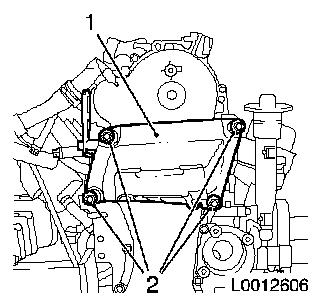
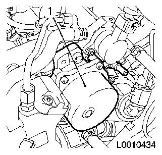
|
| 2. |
Disconnect battery
|
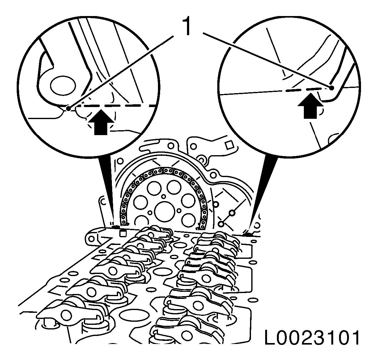
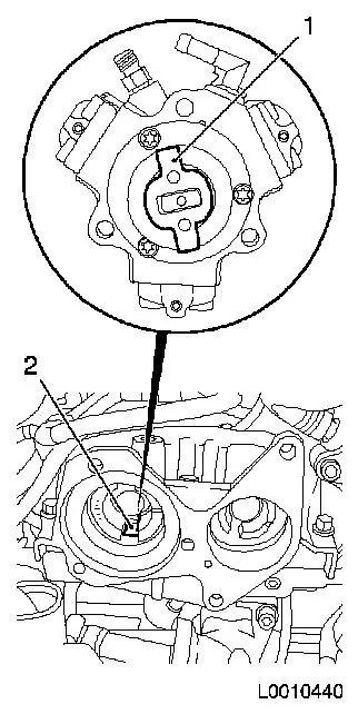
| 3. |
Remove engine cover.
| • |
Detach engine cover
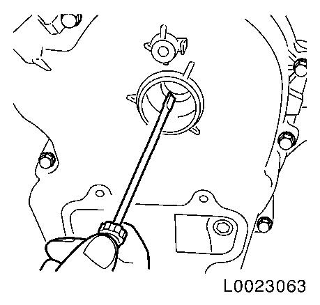
Note: Rubber retainers
must remain on the engine cover.
|
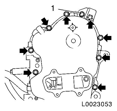
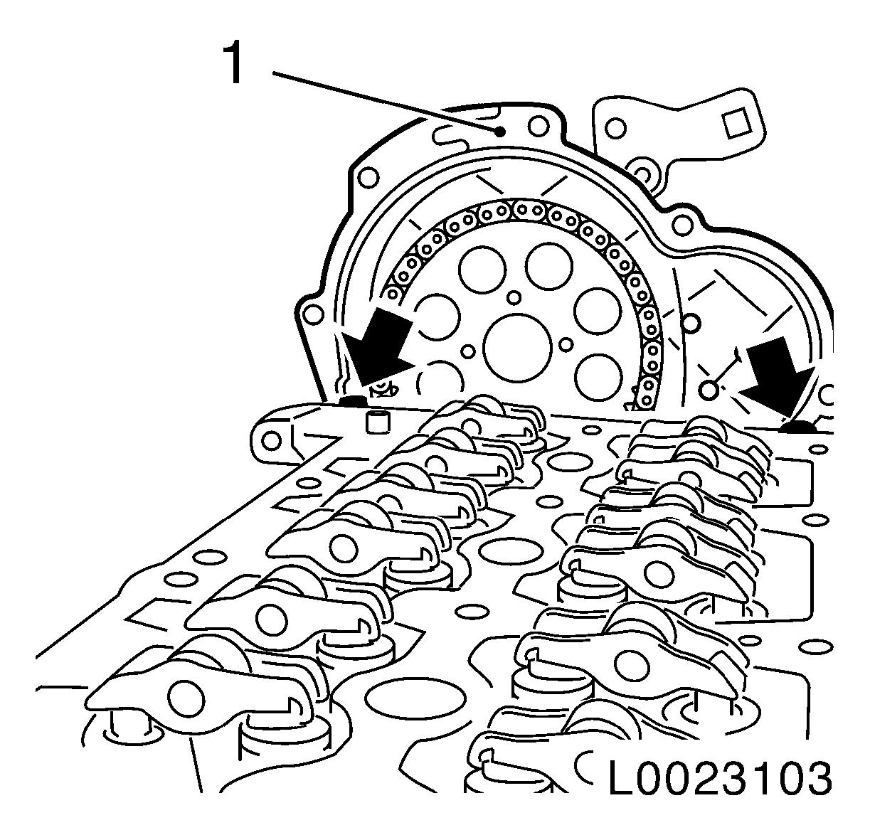
|
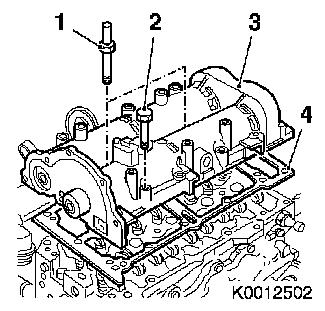
| 4. |
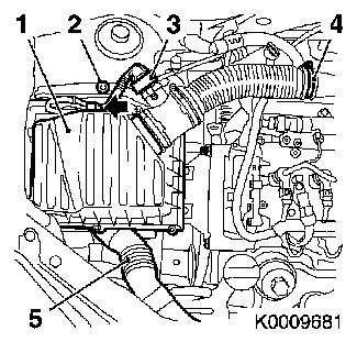
Remove air cleaner housing (1)
| • |
Disconnect wiring harness plug of mass air flow meter (3)
| – |
Unclip from retaining clip (arrow)
|
|
| • |
Detach front intake hose (5)
|
|
|
|
| 5. |
Remove charge air pipe (1)
| • |
Unscrew 2x bolt (arrows)
|
|
|
|
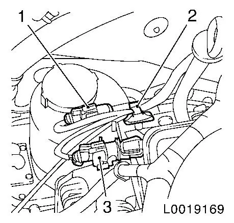
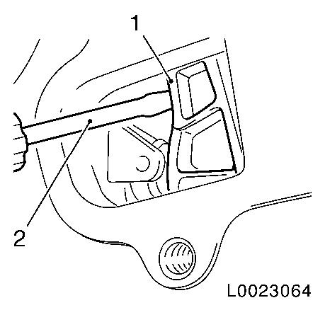
| 6. |
Separate wiring harness plug for differential pressure sensor
(1) and temperature sensor (3)
Note: On vehicles with
diesel particle filter
| • |
Unclip wiring harness from bracket (2)
|
|
|
|
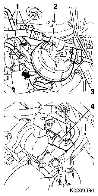
| 7. |
Remove fuel filter housing (2)
| • |
Disconnect 4 lines (1) and (4)
|
| • |
Disconnect 2 wiring harness plugs
|
|
|
|
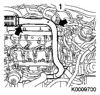
| 8. |
Loosen coolant compensation tank
| • |
Unclip coolant compensation tank
|
|
| 10. |
Remove wiring harness for engine management
| • |
Disconnect 7x wiring harness plugs
| – |
Fuel rail pressure valve
|
| – |
Fuel rail pressure sensor
|
| – |
Starter/alternator wiring harness plug
|
|
| • |
Disconnect wiring harness
|
| • |
Set wiring harness to one side
|
|
| 11. |
Detach 4x high-pressure lines for injectors
|
| 12. |
Detach 2x fuel line (1)
|
|
|
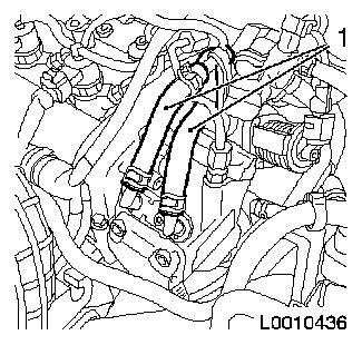
| 13. |
Detach high pressure line (2)
| • |
High-pressure line from high-pressure pump to fuel rail
|
|
| 14. |
Detach accumulator (1)
| • |
Unscrew 2x bolt (arrows)
|
|
|
|
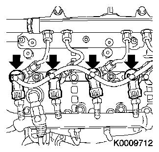
| 15. |
Detach 4x oil leak line
| • |
Release 4x retaining clamp (arrows)
|
|
|
|
| 16. |
Release 2x injector bracket (3)
|
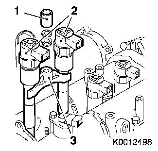
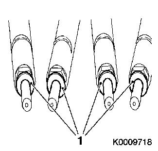
| 17. |
Remove 4 injectors
Note: The injectors (2)
can only be removed in pairs (cylinder 1+2 or cylinder 3+4).
|
|
|
| 18. |
Remove right engine damping block 
|
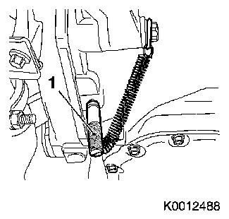
| 19. |
Remove support for engine damping block (1) from cylinder head
and cylinder block
|
|
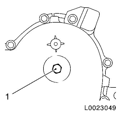
|
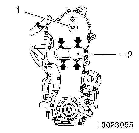
| 20. |
Unscrew closure bolt (1)
|
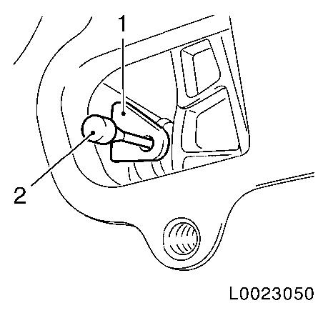
| 21. |
Remove closure cap (2)
| • |
Unscrew 4 bolts (arrows)
|
|
|
|
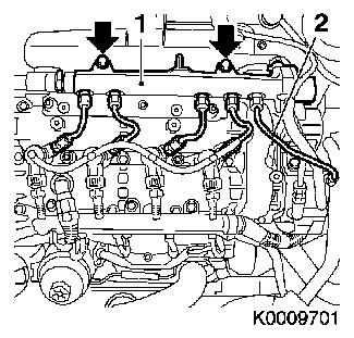
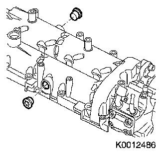
| 22. |
Remove 2 closure bolts from camshaft housing
| • |
Clean 4x threads on closure bolt and camshaft housing
|
|
|
|
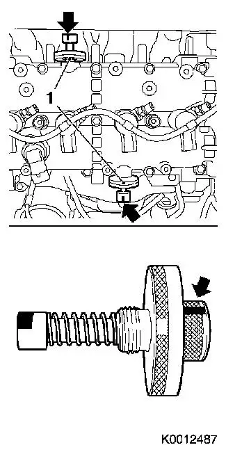
| 23. |
Lock camshafts
| • |
Screw 2x reference drift EN-46781 (1)
into camshafts
Note: Check for proper
installation position!
|
| • |
The reference drift used for fixing must be fitted in a
horizontal position.
Note: As an aid, apply
marking (2) to reference drift.
|
| • |
Turn the camshafts on the camshaft drive pinion screw in
direction of engine rotation until EN-46781 latches into both camshafts
Note: Using a suitable
tool through the opening in the timing case, turn the screw on
camshaft drive gear for exhaust camshaft.
Note: The reference
drift is securely engaged in the camshaft when it can no longer be
turned.
|
|
|
|
| 24. |
Raise vehicle all the way
|
| 25. |
Lock the crankshaft
| • |
Insert EN-46785 (1) through the
opening in the bottom of the gearbox bell housing
|
| • |
To fix EN-46785 , attach screw (2) to
gearbox bolt screw head.
|
| • |
Carefully turn crankshaft until EN-46785 engages in flywheel
|
|
|
|
| 27. |
Detach drive gear for exhaust camshaft
| • |
Detach drive gear screw (1) with suitable tool through the
opening in the timing case.
Note: Do not unscrew
bolt.
|
|
|
|
| 28. |
Tighten timing chain tensioner
| • |
Tighten timing chain tensioner (1) with a suitable tool and
lock in pretensioned position with KM-955-1 (2).
|
|
|
|
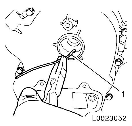
| 29. |
Detach exhaust camshaft drive gear from exhaust camshaft
| • |
Remove drive gear from exhaust camshaft with a rigid angled
wire (1).
|
|
|
|
| 30. |
Detach timing case from camshaft housing
| • |
Unscrew bolt, bracket (1)
|
| • |
Unscrew 8 bolts (arrows)
|
|
|
|
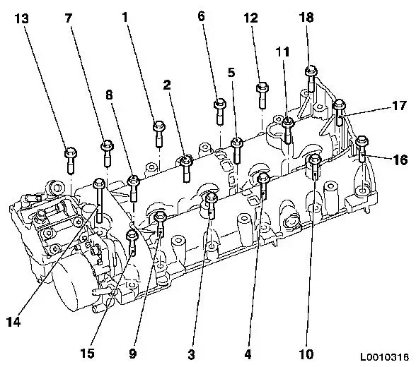
| 31. |
Remove camshaft housing (3)
| • |
Unscrew 16x bolt (2)
Note: Note dissimilar
bolt lengths
|
| • |
Unscrew 2x threaded pin (1)
|
| • |
Carefully detach camshaft housing from timing case using a
rubber mallet
|
| • |
Carefully detach gasket between camshaft housing and timing
case from the camshaft housing using a plastic spatula
|
| • |
Remove camshaft housing
|
|
|
|
| 32. |
Remove timing case gasket
| • |
Cut the elastomer sealing lip (arrow) flush to the cylinder
head using a sharp knife
|
| • |
Detach gasket from timing case with a plastic spatula and
carefully fold up at the nominal break point (1).
|
| • |
Remove gasket residue and thoroughly clean all sealing
surfaces
Note: Ensure that no
gasket residue remains at the joining points between the timing
case and cylinder head, and that no gasket residue drops into the
timing case.
|
|
|
|
| 33. |
Detach vacuum pump (1) from camshaft housing
| • |
Unscrew 2 bolts, vacuum pump
|
|
|
|
| 34. |
Remove high pressure pump (1) from camshaft housing
|
|
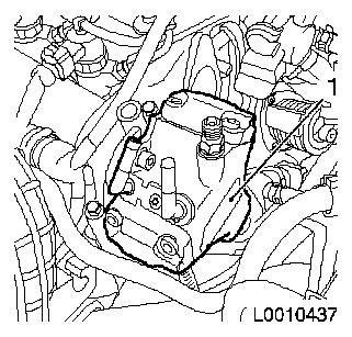
|
| 35. |
Detach camshaft sensor (2)
|
|
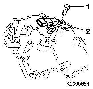
|
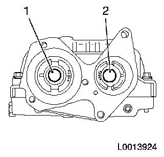
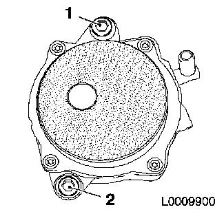
| 36. |
Release 2x pinions, camshaft
| • |
Release bolt (2) pinion, intake camshaft
|
| • |
Release bolt (1) pinion, exhaust camshaft
|
|
|
|
| 37. |
Remove 2 camshaft reference drifts EN-46781
|
| 38. |
Remove intake camshaft
| • |
Remove gear wheel
Note: Pay attention to
mark (IN)
|
|
| 39. |
Remove exhaust camshaft
| • |
Remove gear wheel
Note: Pay attention to
mark (EX)
|
|
 Install
| 40. |
Install exhaust camshaft
| • |
Coat bearing surfaces with engine oil
|
| • |
Insert pinion
Note: Pay attention to
mark (EX)
|
|
| 41. |
Install intake camshaft
| • |
Coat bearing surfaces with engine oil
|
| • |
Insert pinion
Note: Pay attention to
mark (IN)
|
|
| 42. |
Lock camshafts
| • |
Screw 2x reference drift EN-46781 (1)
into camshafts
Note: Check for proper
installation position!
|
| • |
The reference drift used for fixing must be fitted in a
horizontal position.
Note: As an aid, apply
marking (2) to reference drift.
|
| • |
Turn the camshafts on the camshaft drive pinion screw in
direction of engine rotation until EN-46781 latches into both camshafts
Note: Using a suitable
tool through the opening in the timing case, turn the screw on
camshaft drive gear for exhaust camshaft.
Note: The reference
drift is securely engaged in the camshaft when it can no longer be
turned.
|
|
|
|
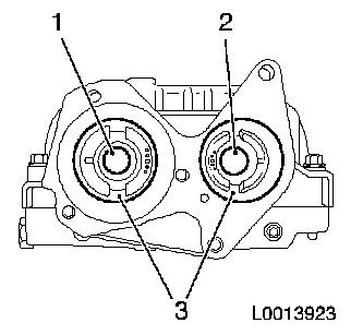
| 43. |
Attach 2x pinions, camshaft
Note: Attach pinions
(3) in position shown!
| • |
Tighten bolt (1) pinion, exhaust camshaft 150 Nm
|
| • |
Tighten bolt (2) pinion, intake camshaft 150 Nm
|
|
|
|
| 44. |
Attach camshaft sensor
|
| 45. |
Attach high pressure pump to camshaft housing
Note: Adapter plate (1)
must engage in groove (2) of camshaft
|
|
|
| 46. |
Install vacuum pump
| • |
Tighten 2 bolts
Note: There are 2 steps
to the tightening sequence
|
|
|
|
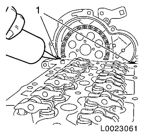
| 47. |
Cut elastomer sealing lip (arrow) at nominal break point of new
gasket using a sharp knife.
|
|
|
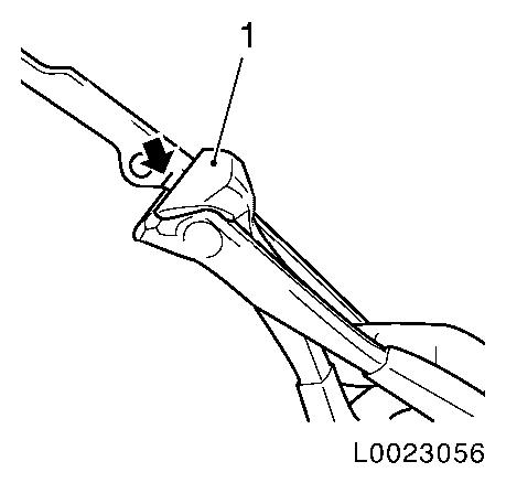
| 48. |
Separate new timing case gasket at lower nominal break
point
| • |
Separate gasket at both nominal break points (arrow) with
pincers (1)
Note: The cutting tool
must have a straight cutting surface.
|
|
|
|
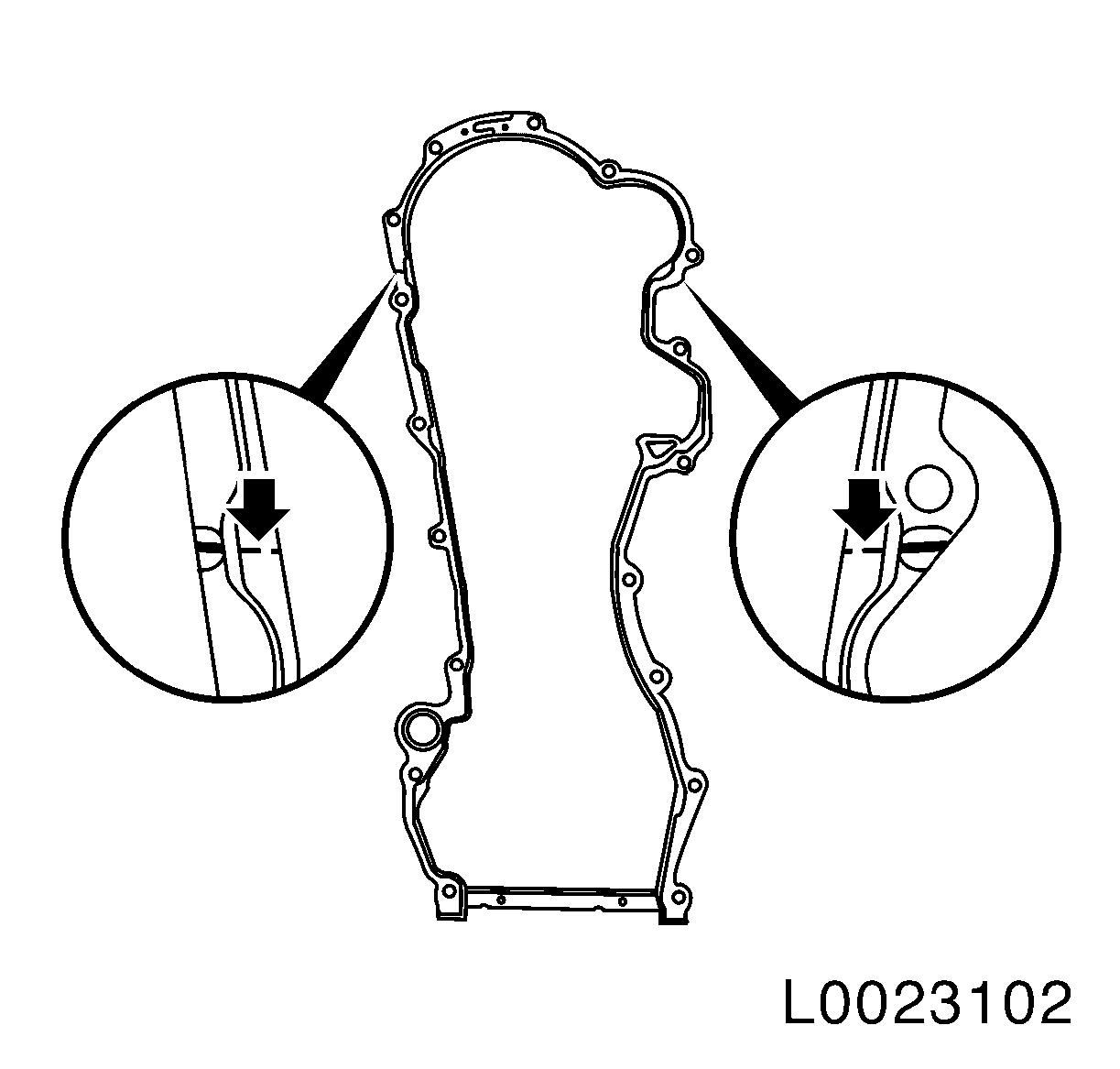
Important: The new upper gasket
and old lower gasket must not overlap!
|
| 49. |
Adapt new seal on timing case
| • |
Adapt the new gasket (1) to the contact surface of cylinder
block to timing case using pincers until the gasket lies flush on
the cylinder head and timing case (arrow), and the holes in the
gasket and timing case align
|
|
|
|
| 50. |
Clean all contact surfaces
|
| 51. |
Attach new camshaft housing gasket
| • |
Clean all contact surfaces
|
| • |
Apply sealant to the contact surface of cylinder head to timing
case (1)
|
| • |
Apply camshaft housing gasket
Note: Check 2x centring
pins
|
| • |
Apply sealant to contact surface of gasket, camshaft housing to
timing case (1)
|
|
|
|
| 52. |
Install camshaft housing
| • |
Unscrew 2x screw connection on timing case gasket
|
| • |
Tighten 16x bolts in tightening sequence until camshaft housing
lies flat on the cylinder head
Note: Do not tighten
bolts yet
Note: Note longer bolt
(14)
|
|
|
|
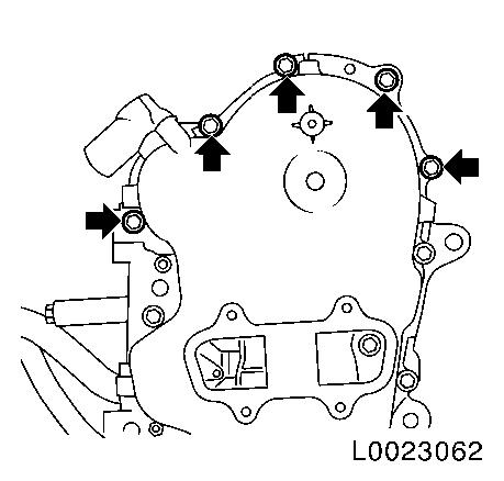
| 53. |
Attach timing case to camshaft housing
| • |
Carefully align camshaft housing to timing case using a rubber
mallet
|
| • |
Screw in 5x bolts (arrows) until camshaft housing lies on
timing case
|
|
|
|
| 54. |
Attach camshaft housing
| • |
Tighten 16x bolts M7 according to tightening sequence 18 Nm
|
| • |
Tighten 2 stud bolts (M8) 25 Nm
|
|
|
|
| 55. |
Attach timing case
| • |
Tighten 8x bolts (arrows) 9 Nm
|
| • |
Screw in bolt (1) bracket, and tighten 9 Nm
|
|
Important: Contact surfaces of
exhaust camshaft, drive gear, bolts and threads in exhaust camshaft
must be free from oil and grease!
|
| 56. |
Insert drive gear for exhaust camshaft
| • |
Lay drive gear on exhaust camshaft with suitable tool
|
| • |
Bolt in bolt
Note: Do not tighten
yet
|
|
|
|
| 57. |
Tension timing chain tensioner
| • |
Release timing chain tensioner with suitable tool and remove
KM-955-1
|
|
| 58. |
Attach drive gear for exhaust camshaft
| • |
Tighten bolt 150 Nm
Note: During tightening
of the timing chain, a second person must tension the timing chain
tensioner (1) with a suitable tool (2).
|
|
|
|
| 59. |
Remove exhaust camshaft lock
| • |
Remove camshaft reference drift EN-46781
|
|
| 60. |
Raise vehicle all the way
|
| 61. |
Remove crankshaft lock
|
| 62. |
Timing, Check
| • |
Turn crankshaft in direction of engine rotation at torsional
vibration damper flange bolt by approx. 700° (2 revolutions)
|
| • |
Fit camshaft reference drift EN-46781
(1) in camshaft housing for exhaust camshaft
|
| • |
Check for proper installation position
Note: The fixing
reference drift must be fitted in a horizontal position. Fit the
guide mark on the reference drift (arrow).
|
| • |
Turn crankshaft in direction of engine rotation until EN-46781 engages in exhaust camshaft
|
| • |
Raise vehicle all the way
|
| • |
Turn crankshaft until EN-46785
engages in flywheel
|
| • |
If EN-46785 does not engage in the
flywheel, repeat the "Timing adjustment" procedure
|
|
| 66. |
Fit exhaust camshaft closure bolt
| • |
Coat closure bolt with thread locking compound
|
| • |
Tighten closure bolt 15 Nm
Note: Complete working
step within 10 minutes because of the reaction time of the thread
locking compound.
|
|
| 67. |
Fit timing case closure cap
| • |
Check gasket for damage
|
|
| 68. |
Install timing case closure bolt
| • |
Check gasket for damage
|
|
| 69. |
Attach support for engine damping block to cylinder head and
cylinder block
| • |
Insert and tighten 4x bolts 60
Nm
|
|
| 70. |
Install right engine damping block
|
| 71. |
Replace 4x seal ring
| • |
For injectors in camshaft housing
|
|
| 72. |
Install 4 injectors
Note: Injectors can
only be inserted in pairs (cylinder 1+2 or cylinder 3+4).
| • |
Replace 4 injector seal rings (1)
|
|
|
|
| 73. |
Fasten 2 injector brackets
|
| 74. |
Attach 4x oil leak line
| • |
Lock 4x retaining clamp
|
|
| 76. |
Attach high pressure line for high pressure pump to fuel
rail
| • |
Tighten union nut (M14) 28 Nm
|
| • |
Tighten union nut (M12) 24 Nm
|
|
| 78. |
Attach 4 high-pressure lines
| • |
Tighten 4 union nuts (M14) 28 Nm
|
| • |
Tighten 4 union nuts (M12) 24 Nm
|
|
| 79. |
Attach wiring harness for engine management
| • |
Connect 7 wiring harness plugs
|
|
| 81. |
Install fuel filter housing
| • |
Connect 2 wiring harness plugs
|
|
| 82. |
Connect wiring harness plug for differential pressure sensor
and temperature sensor
Note: On vehicles with
diesel particle filter
| • |
Clip wiring harness to bracket
|
|
| 83. |
Fasten coolant compensation tank
| • |
Clip in coolant compensation tank
|
|
| 84. |
Install charge air pipe
|
| 85. |
Install air cleaner housing
| • |
Attach front intake hose
|
| • |
Connect wiring harness plug of mass air flow meter
|
|
| 86. |
Install engine cover.
|
| 88. |
Program volatile memory
|
|
