|
Measure crankshaft (Z 10 XE, Z 10 XEP)
| 1. |
Condition: engine dismantled
|
| 2. |
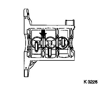
Insert 8 crankshaft bearing shells
| • |
Observe installation position and allocations
|
| • |
Note position of axial bearing (arrow)
|
| • |
In cylinder block, crankshaft bearing cap
|
|
|
|
| 4. |
Attach crankshaft bearing bridge
| • |
Observe installation position and allocations
|
| • |
Tighten 8 bolts
Note: Bolts do not have
to be replaced when checking crankshaft alignment
| – |
Tightening torque 25 Nm + 45° +
15°
|
|
|
| 5. |
Attach MKM-571-B
| • |
Install MKM-571-B in bracket
|
| • |
Fit bracket to transmission side of cylinder block
|
|
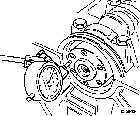
| 6. |
Adjust MKM-571-B
| • |
Attach probe to crankshaft flange
|
| • |
Attach MKM-571-B under
pre-tension
|
|
| 7. |
Measure crankshaft end play
| • |
Move crankshaft in axial direction
|
| • |
Read off test value
Note: Repeat
measurement several times. For permitted crankshaft end play see
"Technical Data - crank drive, cylinder block"
|
|
|
|
| 9. |
Remove crankshaft bearing bridge
| • |
Unscrew 8 bolts
Note: Prise off
evenly
|
|
| 10. |
Attach MKM-571-B
| • |
Attach to cylinder block with bracket
|
|
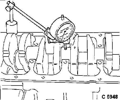
| 11. |
Adjust MKM-571-B
| • |
Place probe against crankshaft bearing journal
|
| • |
Attach MKM-571-B under
pre-tension
|
|
| 12. |
Measure crankshaft concentricity deviation
| • |
Read off test value
Note: For permitted
crankshaft concentricity deviation see "Technical Data - crank
drive, cylinder block"
|
|
|
|
| 15. |
Measure diameter of 4 crankshaft bearing journals
| • |
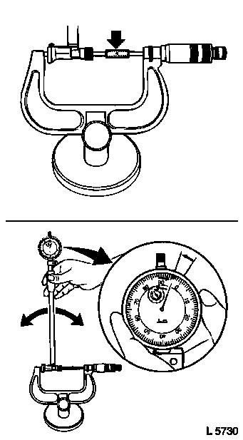
Measure in 2 places per bearing using micrometer gauge
Note: Note dimensions -
if a dimension is outside the permitted tolerance, the crankshaft
must be ground or replaced.
|
|
|
|
| 16. |
Attach 4 crankshaft bearing bridges
| • |
Tighten 8 bolts
Note: Bolts do not have
to be replaced when checking crankshaft alignment
| – |
Tightening torque 25 Nm + 45° +
15°
|
|
|
| 17. |
Set up internal measuring instrument
| • |
Fit appropriate probe tip to internal measuring instrument
| – |
Fit MKM-571-B to internal measuring
instrument with approx. 1 mm of pre-tension
|
|
| • |
Slide internal measuring instrument between micrometer gauge
test surfaces
|
| • |
Determine indicator turning point
| – |
Oscillate internal measuring instrument between test
surfaces
|
| – |
Set MKM-571-B to "0" at turning
point
|
|
|
|
|
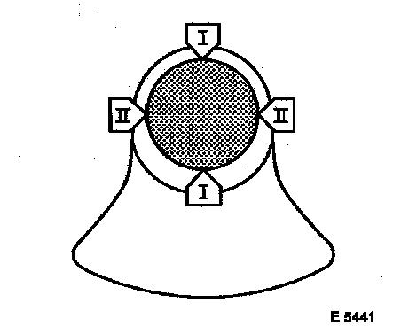
| 18. |
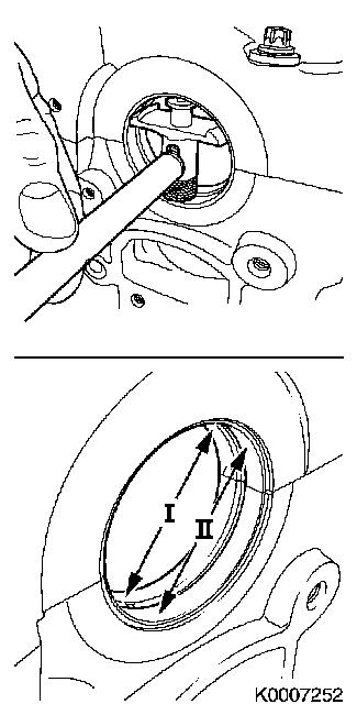
Measure diameter of 8 crankshaft bearing holes
| • |
Determine turning point in 2 places (I+II) per bearing
| – |
Oscillate internal measuring instrument in crankshaft bearing
hole
|
|
| • |
Note down the dimensions
|
|
| 19. |
Calculate crankshaft bearing play (4 times)
Note: The crankshaft
bearing play is calculated on the basis of the difference between
the crankshaft bearing hole and crankshaft bearing journal
diameters. For permitted crankshaft bearing play see "Technical
Data - crank drive, cylinder block"
|
|
|
| 20. |
Remove crankshaft bearing bridge
| • |
Unscrew 8 bolts
Note: Prise off
evenly
|
|
| 21. |
Remove 8 crankshaft bearing shells
|
| 22. |
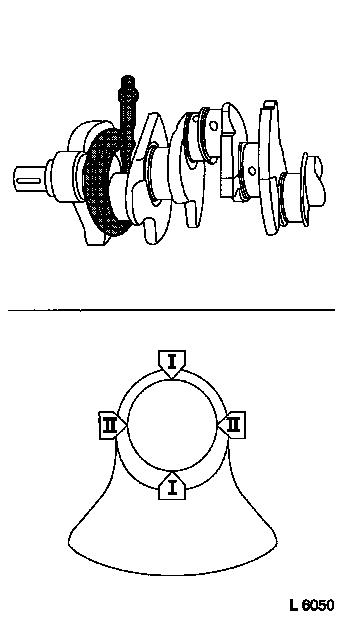
Measure diameter of 3 con-rod journals
| • |
Measure in 2 places (I, II) using micrometer gauge
Note: Note dimensions -
if a dimension is outside the permitted tolerance, the crankshaft
must be ground or replaced.
|
|
|
|
| 23. |
Insert 6 con-rod bearing shells
| • |
Observe installation position and allocations
|
| • |
In con-rod, con-rod bearing cap
|
|
| 24. |
Attach 3 con-rod bearing caps
Important: The mating surfaces of
the cod-rods and con-rod bearing caps form an individual fit and
must not be damaged or interchanged. Do not lay on mating
surfaces
|
| • |
Observe installation position and allocations
|
| • |
Tighten 6 bolts
Note: Bolts do not have
to be replaced when measuring con-rod bearing play.
| – |
Tightening torque 10 Nm + 45° +
15°
|
|
|
| 25. |
Reconfigure internal measuring instrument
| • |
Fit appropriate probe tip to internal measuring instrument
| – |
Fit MKM-571-B to internal measuring
instrument with approx. 1 mm of pre-tension
|
|
| • |
Slide internal measuring instrument between micrometer gauge
test surfaces
|
| • |
Determine indicator turning point
| – |
Oscillate internal measuring instrument between test
surfaces
|
| – |
Set MKM-571-B to "0" at turning
point
|
|
|
| 26. |
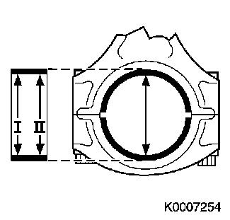
Measure diameter of 3 con-rod bearing holes
| • |
Determine turning point in 2 places (I, II)
| – |
Oscillate internal probe in con-rod bearing hole
|
|
| • |
Note down the dimensions
|
|
|
|
| 27. |
Calculate con-rod bearing play (3 times)
Note: The con-rod
bearing play is calculated on the basis of the difference between
the con-rod bearing hole and con-rod bearing journal diameters. For
permitted con-rod bearing play see "Technical Data - crank drive,
cylinder block"
|
| 28. |
Remove 3 con-rod bearing caps
|
| 29. |
Remove 6 con-rod bearing shells
|
| 30. |
Dismantle internal measuring instrument
|
|
