|
Remove and install crankshaft (Z 14 XE without air
conditioning, Z 16 YNG)
|
1. Remove engine
- Note: See operation "J340100 Engine, Remove and Install"
|
|
2. Remove manual transmission from
engine
- Note: See operation "J340100 007 Manual Transmission, Detach
and Reattach from Engine"
3. Drain engine oil
- Place collecting basin underneath.
- Unscrew oil drain bolt
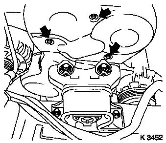
4. Remove upper part of toothed belt cover
- Remove 3 bolts
- Unclip from rear toothed belt cover
|
5. Detach crankshaft ribbed V-belt
pulley
- Block flywheel
- Remove bolt
|
|
|
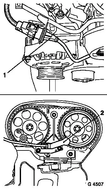
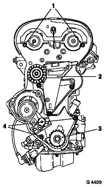
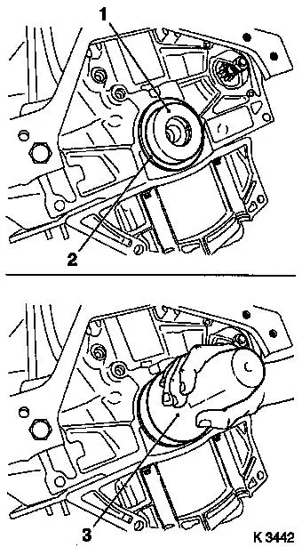
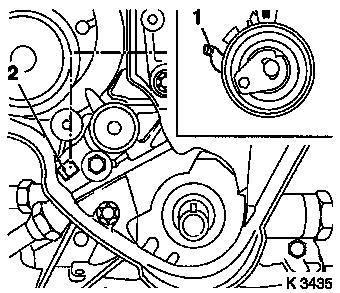
6. Remove camshaft sensor (2)
- Unclip from bracket
- Disconnect wiring harness plug (1)
- Remove 2 bolts
|
|
7. Remove lower part of toothed belt
cover
- Remove bolt
- Unclip from rear toothed belt cover
|
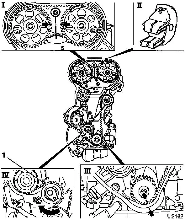
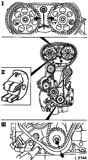
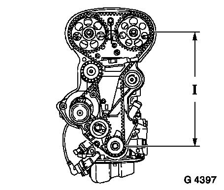
8. Set 1st cylinder to TDC
- Set crankshaft to mark.
- Turn crankshaft evenly
- Note: Marks on crankshaft ribbed V-belt pulley and rear toothed
belt cover must align (III)
- Fix camshaft sprockets in position.
- Note: Marks must be opposite one another and aligned with the
top edge of the cylinder head (I)
- Insert KM-852
|
|
9. Remove toothed belt
- Release toothed belt tension roller (IV)
- Loosen bolt
- Turn adjusting eccentric in direction of arrow (clockwise)
until pointer (1) of the toothed belt tension roller is located
just before left stop.
- Note: Mark running direction
- Remove toothed belt.
|
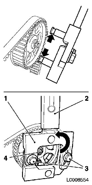
10. Remove camshaft sprocket on exhaust side
- Use KM-6347 (1), KM-956-1 (2)
- Attach KM-6347, KM-956-1
Note: Loosen the
clamping screws (3) of KM-6347 and insert KM-6347 connected to
KM-956-1 in the camshaft sprocket. The notches on KM-6347 must
engage in the camshaft sprocket (arrows). Ensure that it engages
properly.
- Turn KM-6347 in the direction of the arrow using KM-956-1
- Loosen camshaft sprocket bolt (4)
- Remove KM-6347, KM-956-1
- Unscrew camshaft sprocket bolt
|
|
11. Remove camshaft sprocket on intake side
- Use KM-6347, KM-956-1
- Attach KM-6347, KM-956-1
Note: Loosen the
clamping screws of KM-6347 and insert KM-6347 connected to KM-956-1
in the camshaft sprocket. The notches on KM-6347 must engage in the
camshaft sprocket. Ensure that it engages properly.
- Turn KM-6347 in the direction of the arrow using KM-956-1
- Loosen camshaft sprocket bolt
- Remove KM-6347, KM-956-1
- Unscrew camshaft sprocket bolt
|
12. Remove intake side toothed belt
guide roller
|
|
13. Remove exhaust side toothed belt
guide roller
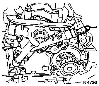
14. Remove right engine bracket (2)
15. Remove toothed belt tension
roller
16. Remove toothed belt drive pulley
(3)
- Unscrew crankshaft ribbed V-belt pulley bolt
- Remove toothed belt drive pulley
17. Remove rear toothed belt cover
18. Remove clutch
Note: See operation
"Remove and install thrust plate and clutch disc (without SAC)" in
group "K"
|
19. Detach flywheel
- Remove 6 bolts
- Detach KM-652
|
|
20. Install oil drain bolt
- Replace seal ring
- Tighten bolt (10 Nm / 7.5 lbf. ft.)
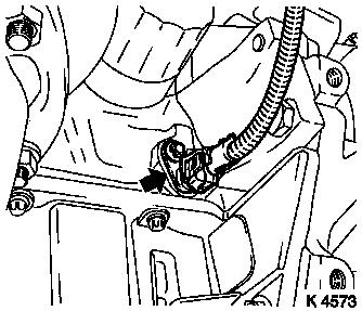
21. Remove crankshaft sensor
- Turn engine (180°)
- Disconnect wiring harness plug (arrow)
- Remove bolt
|
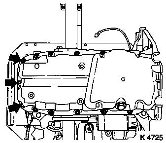
22. Detach oil pan
|
|
|
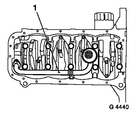
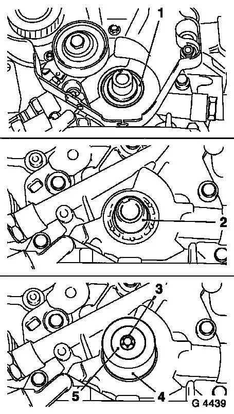
23. Remove oil intake pipe (1)
- Remove 3 bolts
- Remove seal ring
|
|
|
24. Remove oil pump
|
|
|
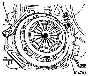
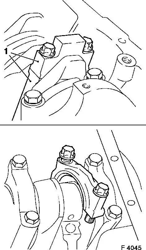
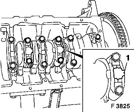
25. Detach con-rod bearing cap
- Mark con-rod bearing cap (1)
- Note: Observe cylinder sequence
- Set piston to BDC position
- 4 off
- Caution: The mating surfaces of the cod-rods and con-rod
bearing caps form an individual fit and must not be damaged or
interchanged. Do not lay on mating surfaces
|
|
|
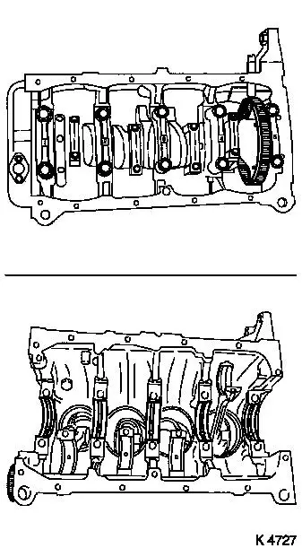
26. Remove crankshaft
- Remove crankshaft bearing cap.
- Mark crankshaft bearing cap
- Note: Observe cylinder sequence
- 5 off
- Remove 10 bolts
- Remove crankshaft rear seal ring
- Note: Place crankshaft on wooden blocks
|
|
27. Remove crankshaft bearing
shells
- Mark crankshaft bearing shells
- Note: Observe cylinder sequence
28. Remove con-rod bearing shells
- Mark con-rod bearing shells
- Note: Observe cylinder sequence
|
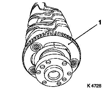
29. Detach crankshaft pulse pick-up
disc (1)
|
|
30. Clean sealing surfaces
- Cylinder block, cylinder head, cylinder head cover, oil pan,
oil pump, crankshaft rear bearing cap
31. Inspect components
- Cylinder block, cylinder head, cylinder head cover, oil pan,
oil intake pipe, oil pump, ribbed V-belt, ribbed V-belt tensioner
assembly, ribbed V-belt pulleys, toothed belt drive
32. Rework threads
- Into cylinder block
- Oil pump
33. Attach crankshaft pulse pick-up
disc
- Tighten bolts (15 Nm / 11 lbf. ft.)
34. Insert con-rod bearing shells
- Caution: Note mark and allocation
- In con-rod, con-rod bearing cap
35. Insert crankshaft bearing
shells
- Caution: Note mark and allocation
- In cylinder block, crankshaft bearing cap
- Caution: Note position of axial bearing
36. Insert crankshaft
- Coat crankshaft journal with engine oil
|
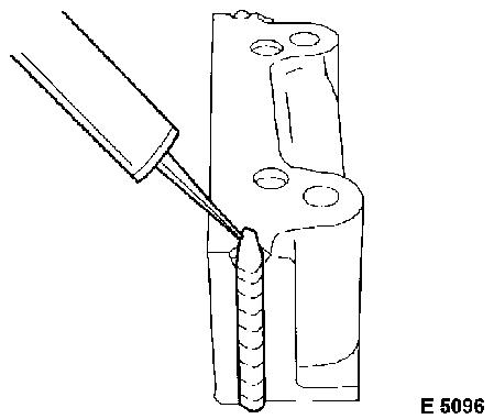
37. Install crankshaft bearing cap
- Caution: Note mark and allocation. Apply sealant in groove of
rear crankshaft bearing cap. Complete assembly operations within 10
minutes
- Renew bolts
- Tighten bolts (50 Nm / 37 lbf. ft. + 45° + 15°)
- Note: Observe tightening sequence
- Remove excess sealant
|
|
|
38. Attach con-rod bearing cap
- Renew bolts
- Caution: Note mark and allocation. Bead (1) on con-rod bearing
cap points towards the transmission side
- Tighten bolts (25 Nm / 18.5 lbf. ft. + 30°)
|
|
|
39. Install rear crankshaft seal
ring
- Coat seal lip with grease
- Position KM-235-6 (1) on crankshaft journal
- Push seal ring (2) onto KM-235-6
- Drive in until flush using KM-658-1 (3)
|
|
|
40. Remove front crankshaft seal
ring
- Lever out seal ring (1)
- Caution: Do not damage sealing surface
|
|
41. Install oil pump
- Replace gasket
- Note: Insert bolts with locking compound
- Tighten bolts (8 Nm / 6 lbf. ft.)
42. Install front crankshaft seal
ring
- Coat seal lip with grease
- Position KM-417 on crankshaft journal (2)
- Push seal ring onto KM-417
- Remove KM-417
- Install crankshaft front seal ring
- With KM-417 (4), bolt (3) and crankshaft ribbed V-belt pulley
(5)
|
43. Install oil intake pipe
- Replace seal ring
- Note: Insert bolts with locking compound
- Tighten bolts (8 Nm / 6 lbf. ft.)
|
|
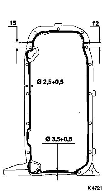
44. Attach oil pan
- Apply sealant
- Caution: Complete assembly operations within 10 minutes
- Screw in bolts
- At cylinder block
- Tighten bolts (10 Nm / 7.5 lbf. ft.)
- At oil pump
- Tighten bolts (10 Nm / 7.5 lbf. ft.)
45. Install crankshaft sensor
- Replace seal ring
- Tighten bolt (10 Nm / 7.5 lbf. ft.)
- Connect wiring harness plug.
46. Rework threads
47. Attach flywheel
- Turn engine (180°)
- Renew bolts
- Tighten bolts (35 Nm / 26 lbf. ft. + 30° + 15°)
48. Install clutch
Note: See operation
"Remove and install thrust plate and clutch disc (without SAC)" in
group "K"
49. Attach rear toothed belt cover
- Tighten bolts (6 Nm / 4.4 lbf. ft.)
50. Install toothed belt drive gear
- Install crankshaft V-belt pulley bolt
|
51. Install toothed belt tension
roller
- Caution: Detent lever (1) of toothed belt tension roller must
engage in guide web (2) of oil pump
- Bolt in bolt
- Note: Only tighten bolt after adjusting toothed belt
tension
|
|
52. Attach right engine bracket
- Renew bolts
- Insert bolts with locking compound (red)
- Tighten bolts (65 Nm + 45° - 60°)
53. Install intake side toothed belt guide roller
- Tighten bolt (25 Nm / 18.5 lbf. ft.)
- Caution: Toothed belt guide roller with larger diameter is
installed on intake side
54. Install exhaust side toothed belt
guide roller
- Tighten bolt (25 Nm / 18.5 lbf. ft.)
|
55. Fix camshaft sprockets in position
- Note: Marks must be opposite one another and aligned with the
top edge of the cylinder head (I)
- Insert KM-852 (II)
- Turn the camshafts at hexagonal section
56. Lock crankshaft
- Set crankshaft to mark.
- Turn crankshaft evenly
- Note: Marks on drive gear toothed belt and rear toothed belt
cover must align (III)
|
|
|
57. Install toothed belt
- Note: Note running direction and timing marks
- Position toothed belt
- Note: Tensioned side must be taut (I)
|
|
|
58. Tension toothed belt
- Tension toothed belt tension roller
- Turn adjusting eccentric in direction of arrow (anticlockwise)
until pointer of the toothed belt tension roller is located just
before left stop
- Fasten toothed belt tension roller bolt (1)
|
|
59. Remove KM-852
|
60. Check timing
- Turn crankshaft (720°)
- At crankshaft ribbed V-belt pulley bolt
- Note: In direction of engine rotation
- Set crankshaft to mark.
- Note: Marks on drive gear toothed belt and rear toothed belt
cover must align (III)
- Insert KM-852 (II)
- Note: Marks must be opposite one another and aligned with the
top edge of the cylinder head (I)
|
|
61. Remove KM-852
|
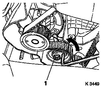
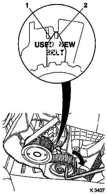
62. Adjust toothed belt tension
- Release toothed belt tension roller
- Turn adjustment eccentric in the direction of the arrow
(clockwise) until pointer (1) is aligned with the notch mark at the
toothed belt tension roller (2).
- Adjust used toothed belts to the marking USED
- Adjust new toothed belts to the marking NEW
- Tighten toothed belt tension roller bolt (20 Nm / 15 lbf.
ft.)
|
|
63. Check toothed belt tension
- Turn crankshaft (720°)
- Note: Pointers on the toothed belt tension roller and notch
mark must align
- Adjust used toothed belts to the marking USED
- Adjust new toothed belts to the marking NEW
64. Rework threads
- Camshaft sensor to cylinder head
65. Install camshaft sensor
- Note: Insert bolts with locking compound
- Tighten bolts (8 Nm / 6 lbf. ft.)
66. Install lower part of toothed belt
cover
- Clip to rear of toothed belt cover
- Tighten bolt (4 Nm / 3 lbf. ft)
67. Install upper part of toothed belt
cover
- Clip to rear of toothed belt cover
- Tighten bolts (4 Nm / 3 lbf. ft)
68. Attach crankshaft ribbed V-belt
pulley
- Block flywheel
- Replace bolt
- Tighten bolt (95 Nm / 70 lbf. ft. + 30° + 15°.)
- Detach KM-652
69. Connect wiring harness plug of
camshaft sensor
- Connect wiring harness plug.
- Clip to bracket
70. Attach manual transmission to
engine
- Note: See operation "J 3401 00 007 Manual Transmission, Remove
and Install from Engine"
71. Install engine
- Note: See operation "J 3401 00 Engine, Remove and Install"
|
