|
Tooth Backlash – Balancer Shaft Unit /
Crankshaft, Check and Adjust
 Remove Remove
|
Remove upper part of oil pan – see operation "Oil Pan
– Upper Part, Remove and Install".
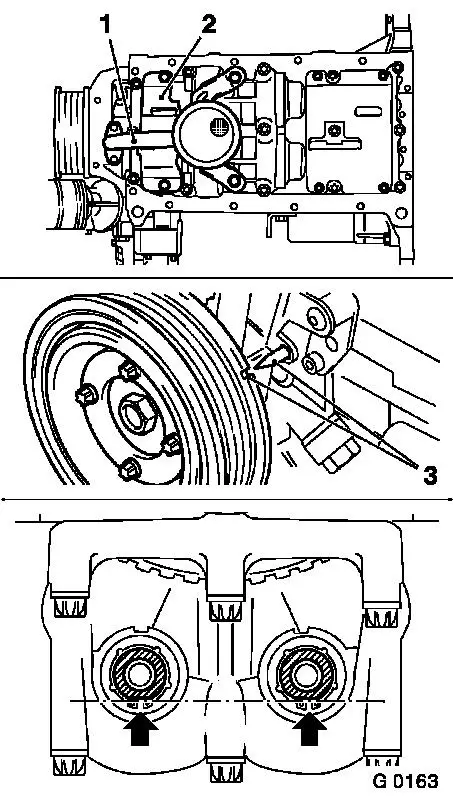
Remove oil intake pipe (1) from oil pump and balancer shaft
unit. Separate oil baffle plate (2) from balancer shaft unit.
 Adjust Adjust
Turn the crankshaft in the direction of engine rotation to the
mark "1st Cylinder TDC" (3) using the fastening bolt for the
toothed belt drive gear.
In this crankshaft position, the flattened sides (arrows) of
both balancer shafts must point down and form a horizontal
line.
|
|
 Install
|
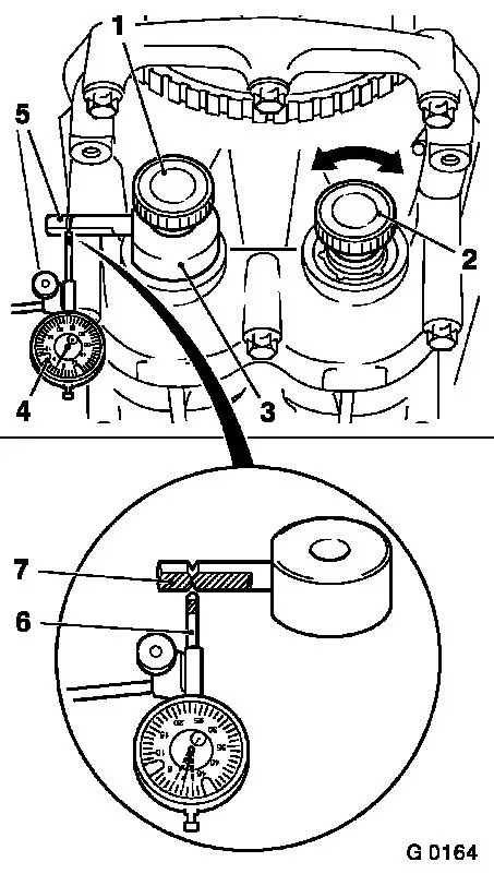
Screw Measuring Device KM-949 (3) with long knurled bolt (1)
into 1st balancer shaft (intake side) and hand-tighten –
measuring arm (5) must point towards "9 o'clock".
Screw short knurled bolt (2) into 2nd balancer shaft (exhaust
side) and also hand-tighten.
Install gauge bracket with Gauge KM-798 (4) to cylinder block
and place probe (6) of gauge against measuring arm of Measuring
Device KM-949 under pre-tension. The probe must be positioned
vertically exactly between the notches on the plane surface
(7).
Determine left and right stop by turning thumb screw (2)
backwards and forwards. Set dial of gauge to zero.
|
|
 Measure
|
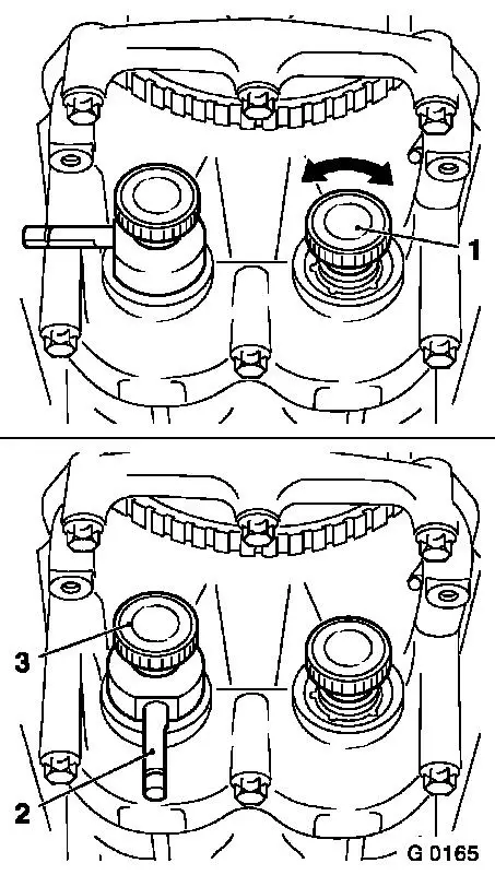
Again use knurled bolt (1) to move 2nd balancer shaft (exhaust
side) back and forth – simultaneously read off tooth backlash
on dial gauge.
Permissible backlash is: 0.02 mm to 0.06 mm.
The tooth backlash must be measured in 4 different positions
– for this, further turn crankshaft at the fastening bolt of
the toothed belt drive gear by 90° in each case in engine
rotational direction until measuring arm (2) is at "6 o'clock".
The loosen the thumb screw (3) and fix measuring arm to "9
o'clock" again and repeat the measurement.
If one of the 4 measurements results in a value outside of the
tolerance range (0.02 mm to 0.06 mm), the tooth backlash must be
adjusted.
|
|
Tooth Backlash – Balancer Shaft Unit /
Crankshaft, Adjust
Remove
Detach balancer shaft unit from
cylinder block / crankshaft bearing cover and remove with balancer
piece. There is an identification number on the balancer piece for
easier allocation. The tooth backlash can also be adjusted using
balancer pieces of varying thickness.
|
Code
|
Thickness of balancer piece in mm
|
|
|
|
|
55
|
0.535 to 0.565
|
|
58
|
0.565 to 0.595
|
|
61
|
0.595 to 0.625
|
|
64
|
0.625 to 0.655
|
|
67
|
0.655 to 0.685
|
|
70
|
0.685 to 0.715
|
|
73
|
0.715 to 0.745
|
|
76
|
0.745 to 0.775
|
|
79
|
0.775 to 0.805
|
|
82
|
0.805 to 0.835
|
|
85
|
0.835 to 0.865
|
Note: The next larger
or smaller balancer piece changes the tooth backlash by approx.
0.02 mm.
Example for selecting the balancer piece: with an installed
balancer piece with the mark "70" a tooth backlash of 0.08 mm was
determined. If a balancer piece with the mark "67" is then
installed, then this produces a tooth backlash of approx. 0.06
mm.
Caution
Only one balancer piece may be installed.
Install
|
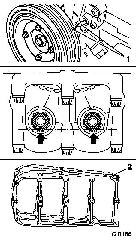
Turn the crankshaft in the direction of engine rotation to the
mark "1st Cylinder TDC" (1) using the fastening bolt for the
toothed belt drive gear.
Turn balancer shafts so that both plane sides (arrows) point
downward and form a horizontal line.
Install selected balancer piece (2) with balancer shaft unit on
cylinder block / crankshaft bearing caps – tighten all
fastening bolts uniformly – tightening torque 20 Nm / 15 lbf.
ft. + 45°.
Measure
Following installation of balancer shaft unit, tooth backlash
must be re-checked and, if necessary, adjusted.
Note: If the balancer
shaft unit needs to be replaced, use the thickest balancer piece
(identification "85") for the initial installation to ensure a
tooth backlash in any case.
|
|
Install
Attach oil baffle plate to balancer shaft unit.
Attach oil intake pipe with new seal ring to oil pump and insert
fastening bolts with bolt locking compound (red) – tightening
torque 8 Nm / 6 lbf. ft. 1)
.
Attach oil intake pipe bracket to
balancer shaft unit.
|
Bolt M6 – tightening torque 10 Nm / 7.5 lbf. ft.
|
|
Bolt M8 – tightening torque 20 Nm / 15 lbf. ft.
|
Upper part of oil pan – see operation "Oil Pan –
Upper Part, Remove and Install".
1 ) The installation time including torque check is
max. 10 min.
|
